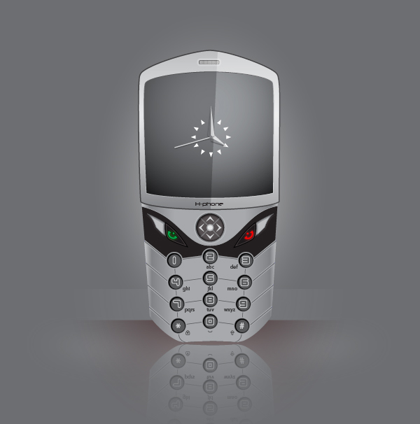
In this tutorial, we will learn how to create a realistic cell phone by using simple shapes and gradients. I will show you working with the Align, the Pathfinder and the Stroke palettes along with the blending objects to reach our last result. So let’s get started.
Create a New Document
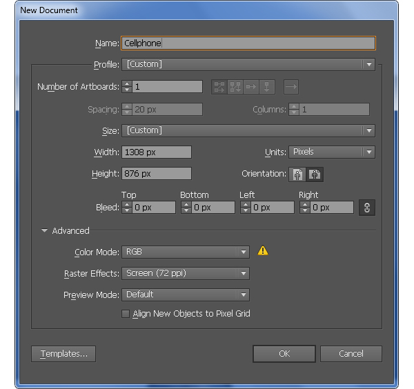
1. Launch Illustrator and then press (Ctrl + N) to create a New document. Select Pixels from the Units drop-down menu, enter 1308 in the width box and 876in the height box then click on the Advanced button. Select RGB, Screen (72ppi) and make sure that the Align New Objects to Pixel Grid box is unchecked before you click OK.
Create the Basic Phone Shape
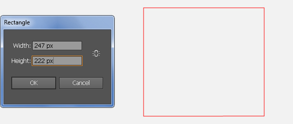
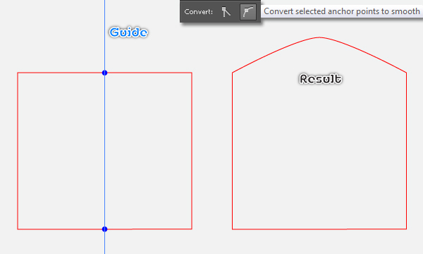
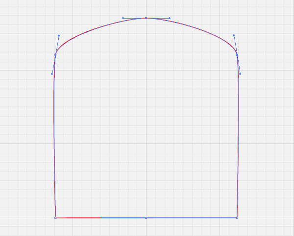
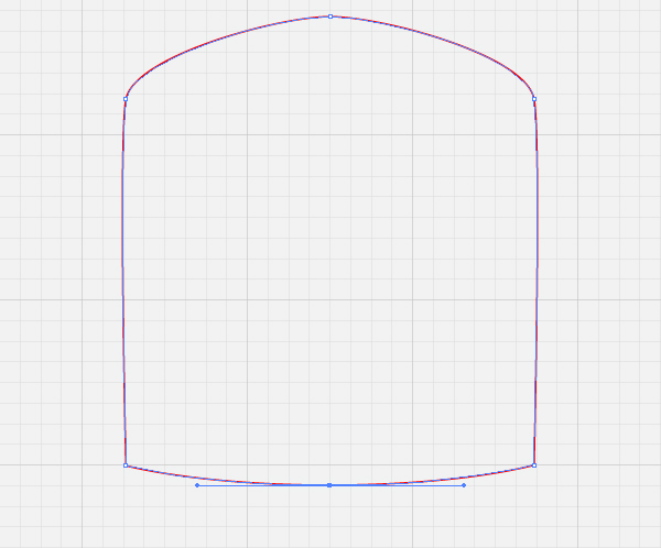
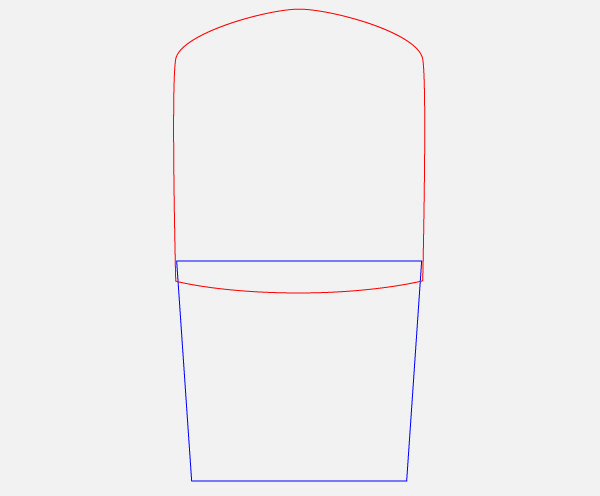
2. Pick the Rectangle Tool (M) and create a 247 by 222px rectangle. Show the Rulers (View > View Rulers > Show Ruler) or (Ctrl +R). Next drag a vertical guide from the Rulers (if the guide locked, go to the View > Guides > Lock Guides) or (Ctrl +Alt + ;). Select the red rectangle, hold down the Shift, click on the newly created guide, release the Shift and then click on the red rectangle again (to fixed its position). Next open the Align palette (Window > Align) and click on the Horizontal Align Center button. Now select the Add Anchor Point Tool (+) and click on the two points highlighted with blue. Next select the top-middle anchor point and move it 50px up, then press the “Covert selected anchor points to smooth” button from the Properties bar. With the help of the Direct Selection Tool (A) and the Shift, adjust the handles of the anchor point just moved like you see in the fourth image. Then select the bottom-middle anchor point and move it 12px down. Finally pick the Convert Achor Point Tool (Shift +C), click on the anchor point just moved, hold mouse and drag it to the left while holding Shift. In the end your new object should look like the final image shown.
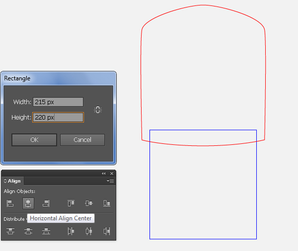
3. With the Rectangle Tool (M) create a 215 by 220px rectangle and then place it to the position as shown below. Now select the red object created in the step 2, hold down the Shift, click on the blue rectangle created in this step, release the Shift and click on the red object again (to fixed its position), then click on the Horizontal Align Center button from Align palette. Select the top-left anchor point of the blue rectangle and move it 15px to the left. Then select the top-right anchor point and move it 15px to the right.
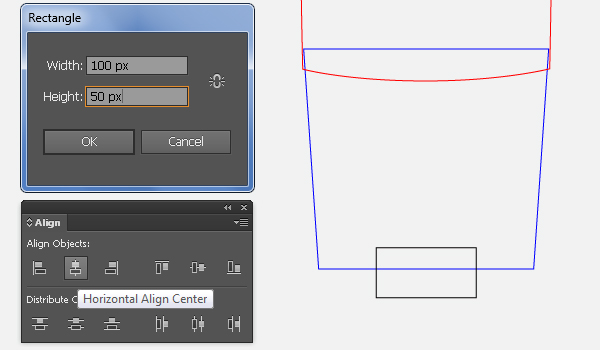
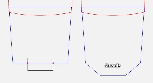
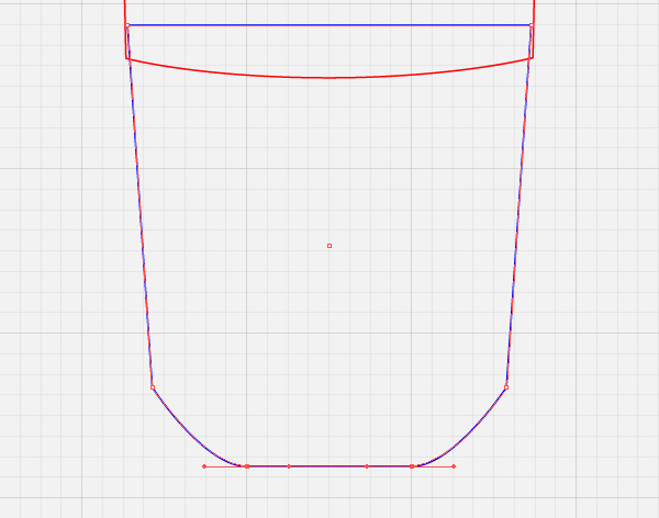
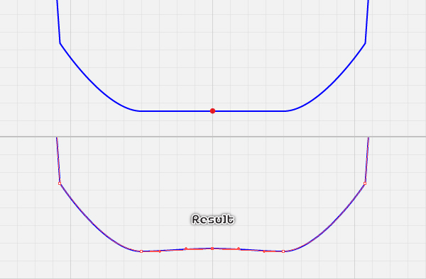
4. Pick the Rectangle Tool (M) and create a 100 by 50px black rectangle, then place it to the position as shown below. Now select the blue object created in the step 3, hold down the Shift, click on the black rectangle created in this step, release the Shift and click on the blue object again (to fixed its position), then click on the Horizontal Align Center button from Align palette. With the help of the Add Anchor Point Tool (+) add two anchor points highlighted with red for the blue object. Remove the black rectangle, then reselect the two newly created anchor points and move them 48px down. Pick the Convert Achor Point Tool (Shift +C), click on the bottom-left anchor point of the blue object, hold mouse and drag it to the right while holding Shift. Repeat the same techniques for the bottom-right anchor point. Next focus on the fifth image, pick the Add Anchor Point Tool (+) and add an anchor point highlighted with red, then move this anchor point 2px up.
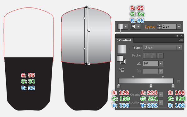
5. After you are done adjusting the shape of the blue object, reselect this object and fill it with R=35, G=31, B=32. Next select the red object and fill it with the linear gradient as shown below, then add a 2px stroke (R=65, G=64, B=66).
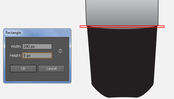
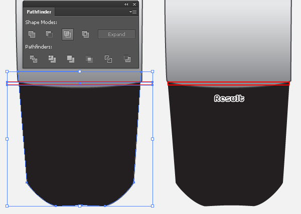
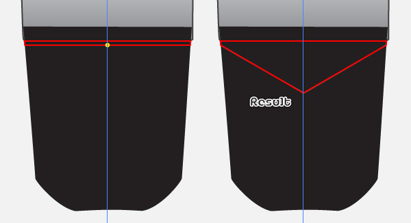
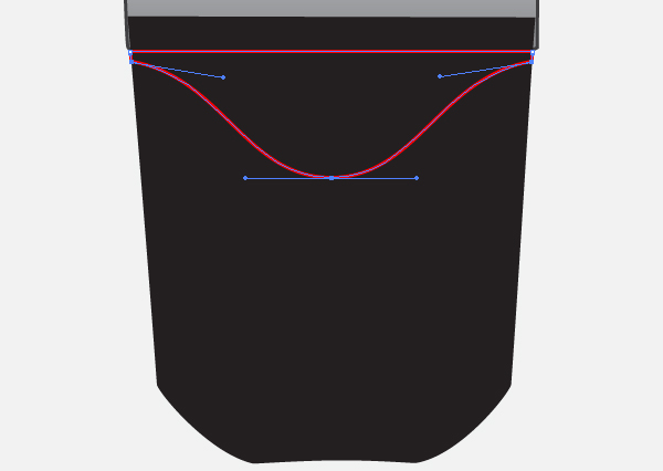
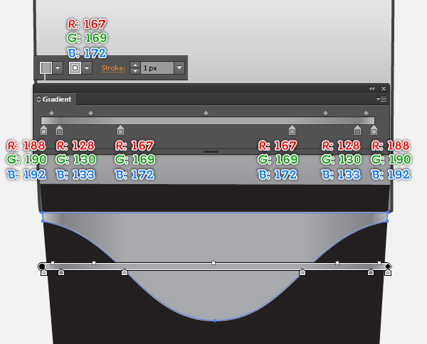
6. Using the Rectangle Tool (M) create a 290 by 6px red rectangle and then place it to the position as shown below. Select the black shape created in the step 5 and make a copy (Ctrl +C, Ctrl +F) of it. Still having this copy selected, hold down the Shift and click on the red rectangle created in this step. Then open the Pathfinder palette (Window > Pathfinder) and click on the Intersect button. With the Add Anchor Point Tool (+) add an anchor point highlighted with yellow for the red object, then move the newly created anchor point 70px down. With the help of the Convert Anchor Point Tool (Shift +C) adjust the shape of the red object to get the result like you see in the sixth image. After you are done adjusting the shape of the red object, apply a nice linear gradient as it is shown in the final image below.
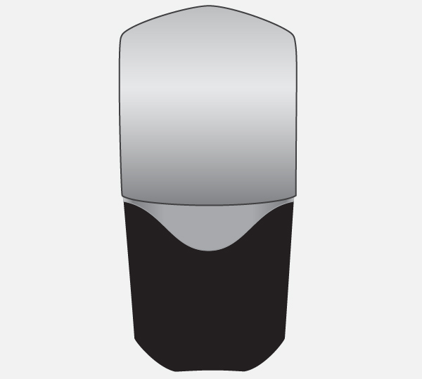
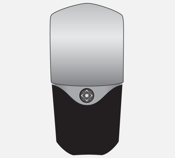
7. At this point your cell phone should look like in the next image:
Create the Joystick Button
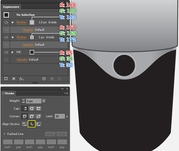
8. Start with drawing a 56 by 56px red ellipse using the Ellipse Tool (L), then place this ellipse to the correct position as shown below. Fill the newly created ellipse with R=35, G=31, B=32 and add a 3px Stroke (R=167, G=169, B=172) for it. Keep this ellipse selected, open the Stroke palette (Window > Stroke) and click on the “Align Stroke to Inside” icon. Still having the ellipse created in this step selected, open the Appearance palette (Window > Appearance), click on the Add New Stroke button (at the left-bottom corner of the Appearance palette). This will add a second stroke for your ellipse. Fill it with R=188, G=190, B=192 and change the stroke weight to 1.5px.

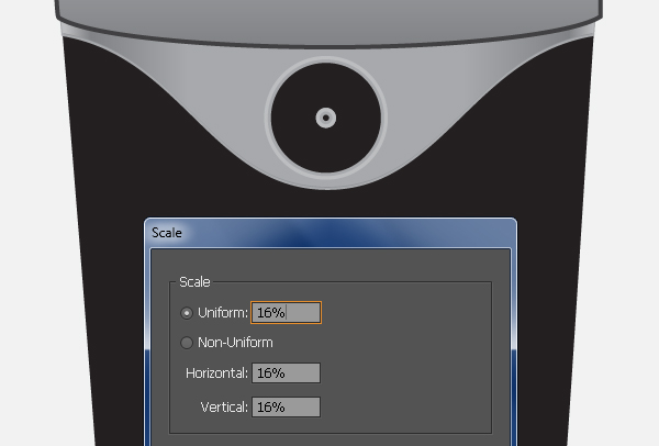
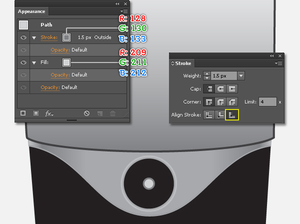
9. Select the ellipse created in the step 8 and go to the Object > Transform > Scale… Check the Uniform and enter a 16 in the Scale box, then click Copy. Having the newly created ellipse selected, open the Appearance palette (Window > Appearance) and remove the 3px stroke of this ellipse. Next replace the existing stroke color of the ellipse with R=128, G=130, B=133 and replace the existing fill color of it with R=209, G=211, B=213. Make sure that the resulting ellipse is still selected, open the Stroke palette (Window > Stroke) and click on the “Align Stroke to Outside” icon.
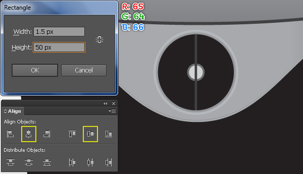
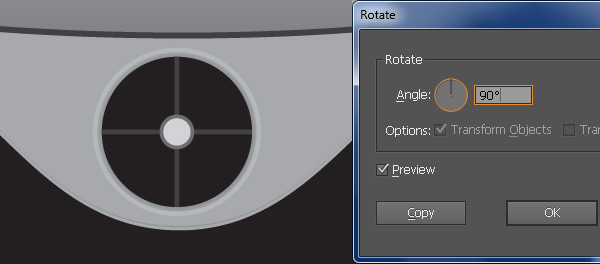
10. Pick the Rectangle Tool (M) and create a 1.5 by 50px rectangle (R=65, G=64, B=66). Select the ellipse created in the step 9, hold down the Shift, click on the newly created rectangle, release the Shift and then click on the ellipse created in the step 9 again (to fixed its position). Next open the Align palette (Window > Align) and click on the Horizontal Align Center button, then click on the Vertical Align Center button. Reselect the rectangle created in this step and go to the Object > Transform > Rotate… Enter a 90 degrees Angle and click Copy. Finally select the two rectangles created in this step and hide them behind the ellipse created in the step 9.
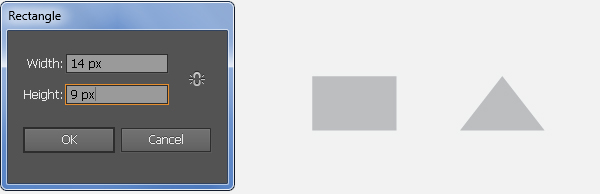
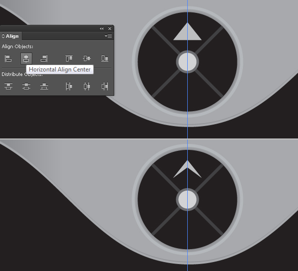
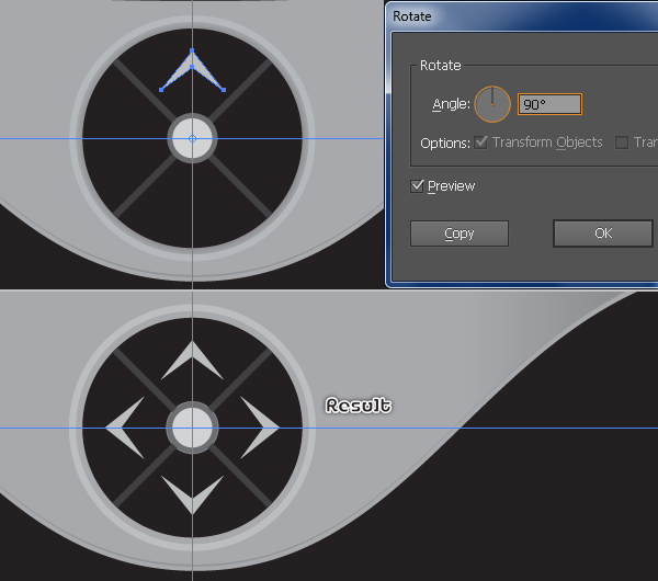
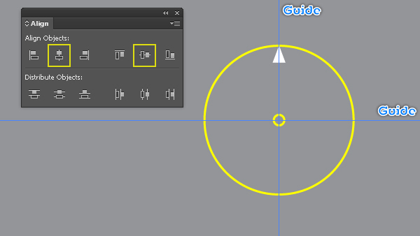
11. Pick the Rectangle Tool (M) and create a 14 by 9px rectangle (R=199, G=190, B=192). Select the top-left anchor point of the newly created rectangle and remove it. Then select the top-right anchor point and move it 7px to the left. Place the newly created triangle to the correct position as shown in the third image. With the Add Anchor Point Tool (+) click on the center of the bottom of the triangle, then move the newly created anchor point 5px up. Next drag a horizontal guide from the Rulers. Select the ellipse created in the step 9, hold down the Shift, click on the horizontal guide, release the Shift and then click on the ellipse created in the step 9 again (to fixed its position). Next open the Align palette (Window > Align) and click on the Vertical Align Center button. Now reselect the white shape created in this step, pick the Rotate Tool (R), hold down the Alt key and click on the intersection point of the two guides. In the Rotate dialog box, enter a 90 degrees Angle and click Copy, then press (Ctrl +D) twice to get the results as shown in the sixth image.
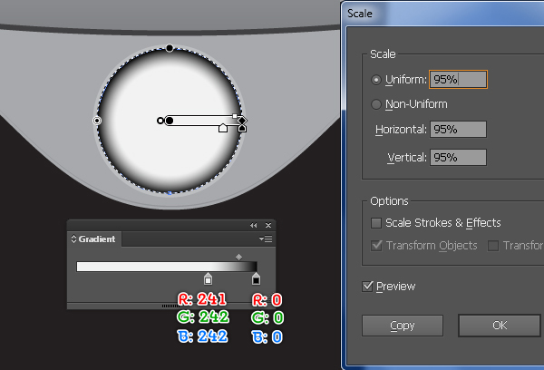
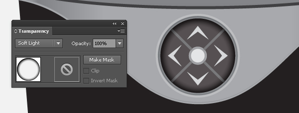
12. Select the ellipse created in the step 8 and go to the Object > Transform > Scale… Check the Uniform and enter a 95 in the Scale box, then click Copy. Bring this copy to front (Ctrl +Shift +Right Square Bracket) and fill it with the radial gradient as shown below, then remove the stroke of it. Next change the Blendding Mode of the resulting ellipse to Soft Light. At this point your cell phone should look like in the final image below.
Create the Call and the Cancel Button
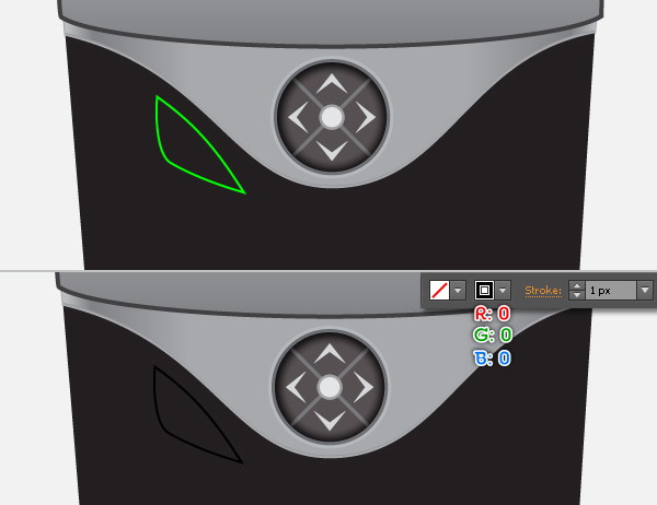
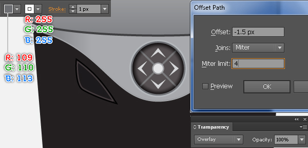
13. With the Pen Tool (P) create a green object as shown below. Once your object is drawn, fill it with none and add a 1px stroke (R=0, G=0, B=0). Reselect the newly created object and go to the Object > Path > Offset Path… Enter a -1.5px Offset and click OK. Fill the newly created object with R=109, G=110, B=113 and replace the existing stroke color of it with R=255, G=255, B=255. Finally change the Blendding Mode of the resulting shape to Overlay.
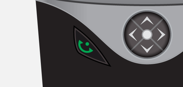
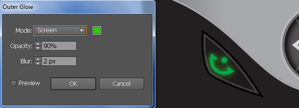
14. With the help of the Pen Tool (P) and the Ellipse Tool (L), create two green shapes like you see in the image below. Reselect these two shapes and go to the Effect > Stylize > Outer Glow… Follow the data as shown in the second image and click OK.
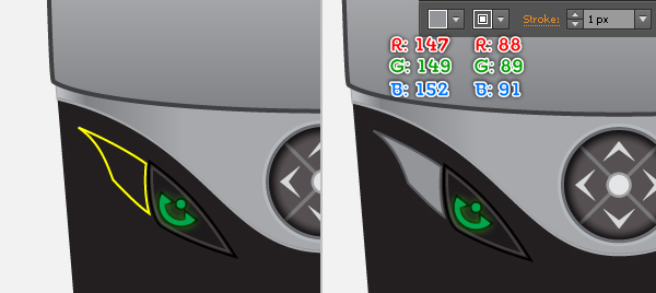
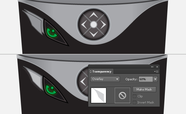
15. Continue create another object using the Pen Tool (P) like in the image. Once your object is drawn, fill it with R=147, G=149, B=152 and then add a 1px stroke (R=88, G=89, B=91). Still having the resulting shape selected and make a copy (Ctrl +C, Ctrl +F) of it. Next move this copy 2px down and then move it 3px to the left. Finally change the Blendding Mode of the newly created shape to Overlay and reduce its Opacity to 60%.
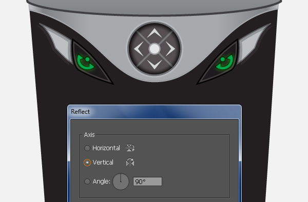
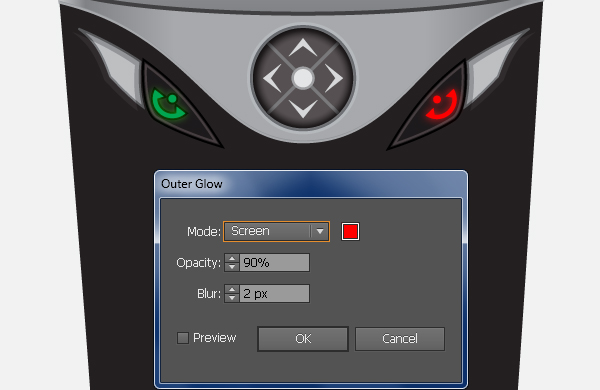
16. Before you continue, select and group (Ctrl +G) all objects created from beginning step 13 to this time. Having this group selected and go to the Object > Transform > Reflect. Set the Axis to Vertical and then click Copy. Drag the copy we have just created to the right. Don’t forget to hold the Shift key on the keyboard for straight dragging. Next pick the Selection Tool (V), double-click on the newly created group and replace the existing color of the two green shapes with red. Reselect these two red shapes and open the Appearance palette (Window > Appearance), then click on the Outer Glow section. In the Outer Glow dialog box, follow the data as shown in the second image. At this point your cell phone should look like in the final image below.
Create the Zone containing the Buttons with the Ciphers
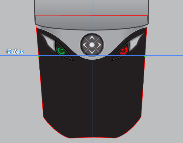
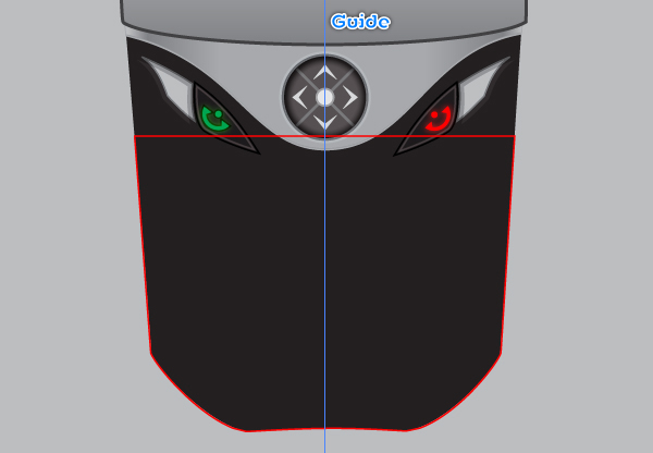
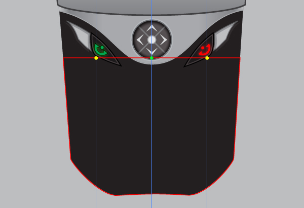
17. Drag a horizontal guide from the Ruler to the position as shown below. Select the black shape created in the step 5 and make a copy of it, then bring the copy to front. Remove the fill color of this copy and add a 1px red stroke. With the Add Anchor Point Tool (+), add two anchor points highlighted with green for the red object. Next select the two top anchor points of the red object and remove them. The resulting object should look like the second image below. Now select the vertical guide created in the step 2 and make two copies (Ctrl +C, Ctrl +F, Ctrl +F) of it. Select a newly created guide and move it 73px to the left. Then select the remaining newly created guide and move it 73px to the right. Focus on the third image, add three anchor points highlight with yellow and green for the red object. Next select the two anchor points highlighted with yellow and move them 35px down. Then select the anchor point highlighted with green and move it 25px down.
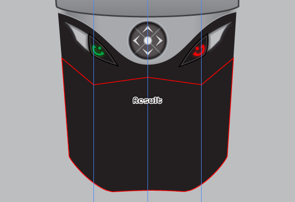
18. Select two newly created guides and remove them. Then hide the vertical guide created in the step 2. Now select the anchor point highlighted with green of the left side of the red object and move it 1px to the left. Then select the anchor point highlighted with yellow of the left side and move it 2px to the left. Repeat the same process for the right side of the red object. The resulting object should look like the second image below. Finally reselect the red object, remove the stroke color of it and then fill it with the linear gradient like you see in the third image.
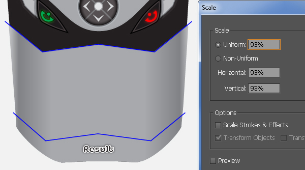
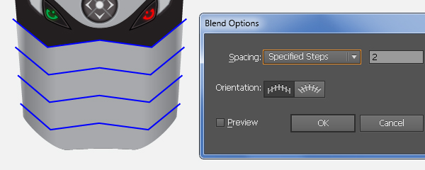
19. Pick the Pen Tool (P) and create a zig zag path as shown below. Once your path is drawn, reselect it and go to the Object > Transform > Scale… Check the Uniform, enter a 93 in the Scale box and click Copy, then move the copy down to the position as shown in the second image. Reselect the two newly created paths and go to the Object > Blend > Blend Options… Follow the data as shown in the third image and click OK, then go to the Object > Blend > Make (Ctrl +Alt +B). Continue with the Pen Tool (P) create two paths like you see in the final image.
Create the Buttons
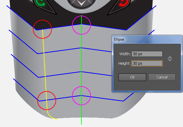
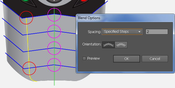
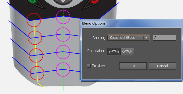
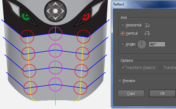
20. With the help of the Ellipse Tool (L) create four 30 by 30px magenta ellipses. Reselect two newly created ellipses and replace the existing stroke color of them with red, then place these four ellipses to the correct positions as shown below. Then select the two magenta ellipses and go to the Object > Blend > Blend Options… Follow the data as shown in the second image and click OK, then go to the Object > Blend > Make (Ctrl +Alt +B). Next create a blend between two red ellipses. Now reselect the red blended object and the yellow curved path, then go to the Object > Transform > Reflect. Set the Axis to Vertical and then click Copy. Drag the copies we have just created to the right. Don’t forget to hold the Shift key on the keyboard for straight dragging.
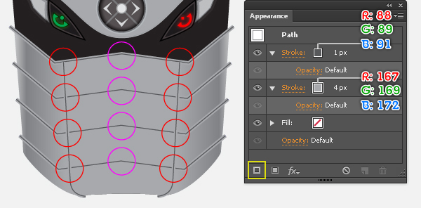
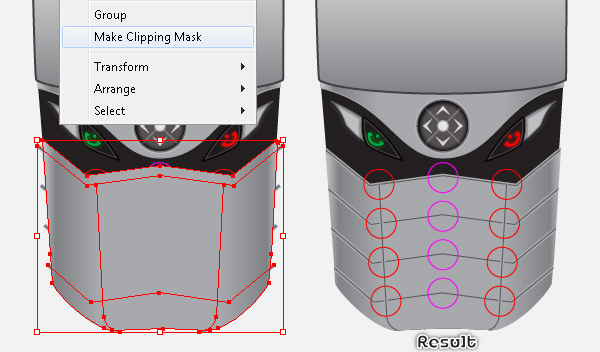
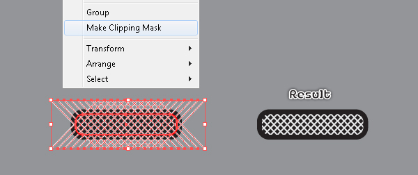
21. Select and group (Ctrl +G) the blue blended object and the two yellow curved paths created in the previous steps. Then fill the newly created group with no fill and add a 4px stroke (R=167, G=169, B=172) for it. Keep this group selected, open the Appearance palette (Window > Appearance), click on the Add New Stroke button (at the left-bottom corner of the Appearance palette). This will add a second stroke for your group. Fill it with R=88, G=89, B=91 and change the stroke weight to 1px. Now select the shape created in the step 18 and make a copy of it, then bring the copy to front (Ctrl +Shift +Right Square Bracket). Next select five upper anchor points of the newly created shape and move them 10px up. Reselect this shape and the group created in this step, then go to the Object > Clipping Mask > Make (Ctrl +7). Finally hide this clipping set behind the twelve ellipses created in the previous steps.
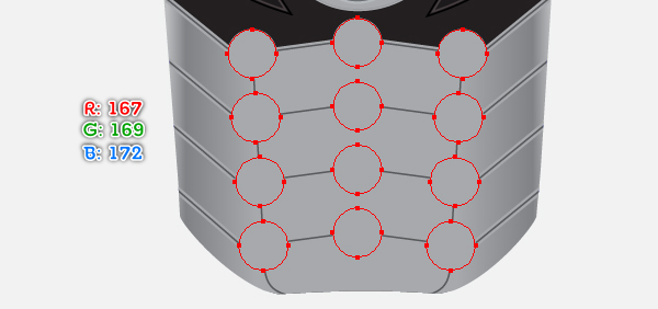
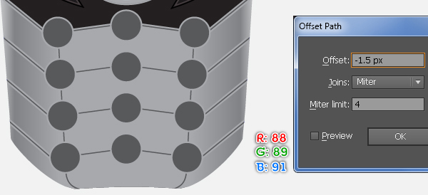
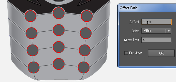
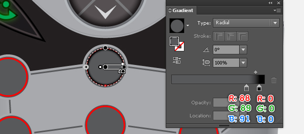
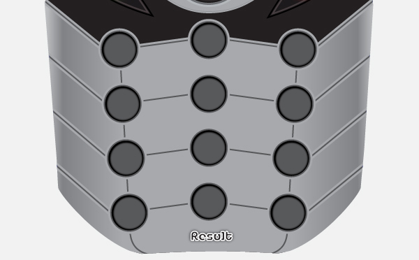
22. Select the two red blended objects and the magenta blended object, then go to the Object > Expand… Click OK when the Expand dialog box appear, then press (Ctrl +Shift +G) to ungroup the three resulting groups. Still having the newly created ellipses selected and fill them with R=167, G=169, B=172, then remove their strokes. Keep the resulting ellipses selected and go to the Object > Path > Offset Path… Enter a -1.5px Offset and click OK, then replace the existing fill color of the newly created ellipses with R=88, G=89, B=91. Make sure that the resulting ellipses are still selected and go to the the Object > Path > Offset Path… Enter a -1px Offset and click OK. Then add a 1px red stroke for the newly created ellipses and remove their fill color. Now select the top-middle red ellipse and fill it with the radial gradient as shown in the fourth image, then remove the stroke color of it. Finally select all remaining red ellipses, then pick the Eyedropper Tool (I) and click on the ellipse you just filled with the radial gradient. At this point your buttons should look like in the final image below.
Adding the Numbers
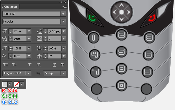
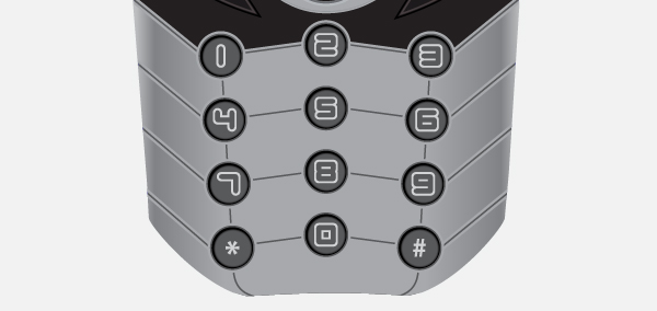
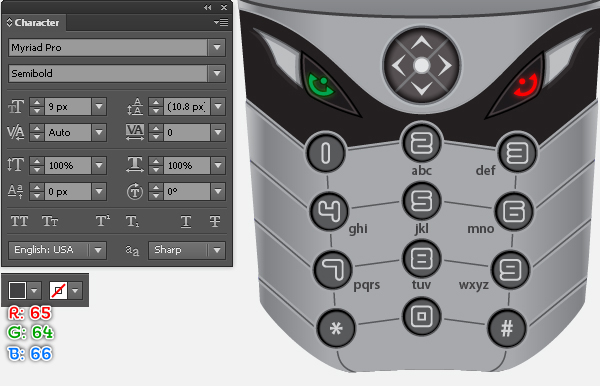
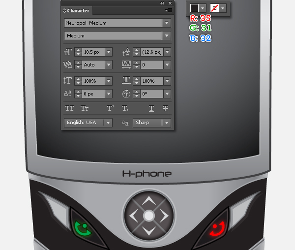
23. Open the Character palette (Window > Type > Character) and set the data as shown below. Next open the Paragraph palette (Window > Type > Paragraph) and click on the Align Center button. Now pick the Type Tool (T), simply click on your artboard and type the numbers, then place them to the correct positions like you see in the first image. Finally add two symbols as shown in the second image.
Adding the Letters
24. Do the same as the previous step to add the letters on the zone containing the buttons (but with another font). Next add some symbols like you see in the second image.
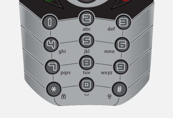
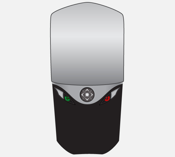
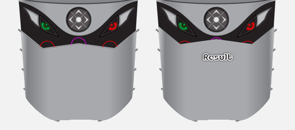
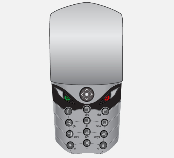
25. At this point your cell phone should look like in the next image:
Create the Phone Screen
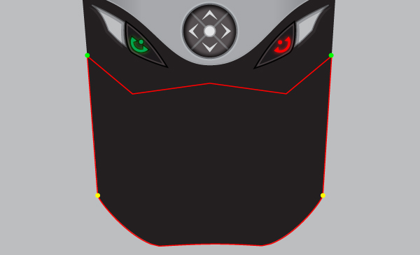
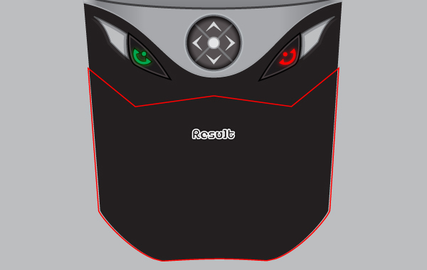
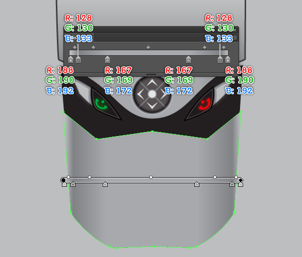
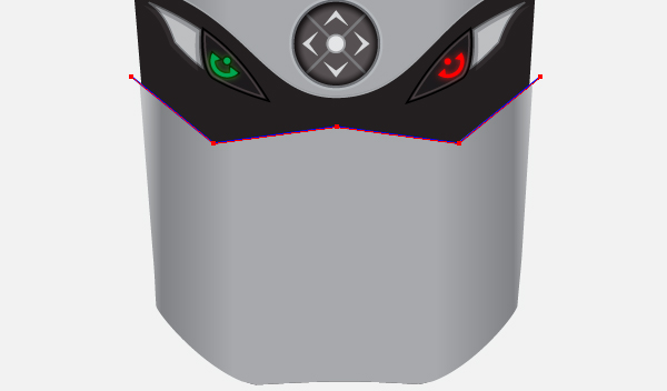
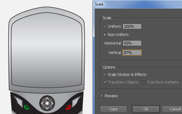
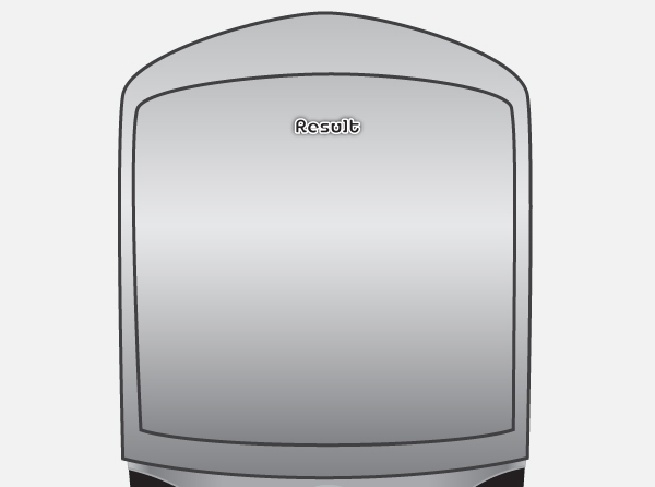
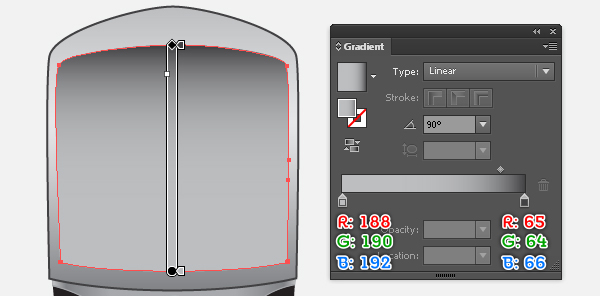
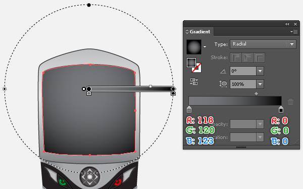
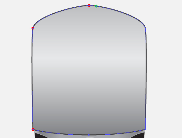
26. Select the upper shape created in the step 5 and go to the Object > Transform > Scale… Check the Non-Uniform, enter a 93 in the Horizontal box and enter a 87 in the Vertical box, then click Copy. Next select the top anchor point of the newly created shape and move it 19px down. Reselect the newly created shape and remove the stroke color of it, then replace the existing color of this shape with new linear gradient as shown in the third image. Still having the resulting shape selected and make a copy (Ctrl +C, Ctrl +F) of it, then replace the existing color of the copy with the radial gradient like you see in the final image.
Create the Loud Speaker
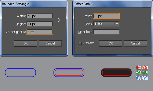
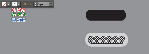
27. Pick the Rounded Rectangle Tool and simply click on your artboard. Follow the data as shown below and click OK, then go to the Object > Path > Offset Path… Enter a -2px Offset and click OK, then replace the existing stroke color of the newly create object with red. Reselect the blue rectangle and fill it with R=35, G=31, B=32, then remove the stroke color of the resulting rectangle.
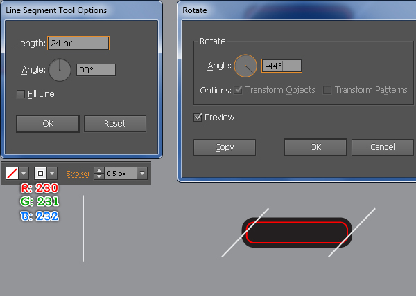
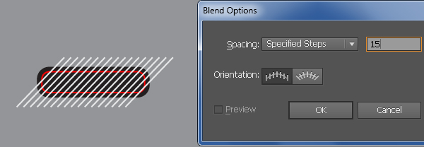
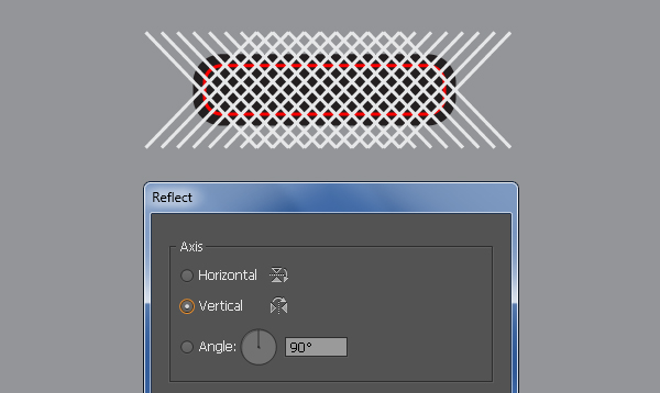
28. Using the Line Segment Tool (\) create a vertical line of length 24px, with a 0.5px stroke (R=230, G=231, B=232) and no fill, then rotate this line an angle of about -44 degrees. Make a copy (Ctrl +C, Ctrl +F) of this line and then place them to the positions as shown in the second image. Reselect these two lines and go to the Object > Blend > Blend Options… Follow the data as shown in the third image and click OK, then go to the Object > Blend > Make (Ctrl +Alt +B). Still having the blended object selected and go to the Object > Transform > Reflect… Check the Vertical and click Copy. Now select the red rounded rectangle created in the step 27, bring it to front (Ctrl +Shift +Right Square Bracket) and make a copy of it, then hide (Ctrl +3) the copy. Reselect the red original rectangle, hold down the Shift and click on the two blended objects created in this step, then go to the Object > Clipping Mask > Make (Ctrl +7).
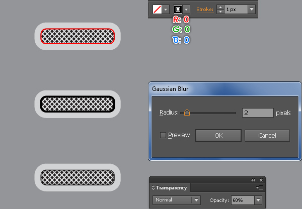
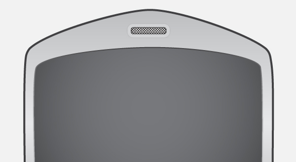
29. Select the black rectangle created in the step 27 and make a copy of it, then bring the copy to front. Having this copy selected, remove the fill color of it and then add a 3px stroke (R=209, G=211, B=212). Before you continue, press (Ctrl +Alt +3) to show the red rectangle hidden in the step 28. Next replace the existing stroke color of it with R=0, G=0, B=0, then apply a 2px Gaussian Blur effect for the resulting rectangle and reduce its Opacity to 60%. Finally select and group (Ctrl +G) all objects created from beginning step 27 to this time, then place this group to the position as shown in the final image.
Create the Phone Logo
30. It’s time to create the logo of the cell phone. Open the Character palette (Window > Type > Character) and set the data as shown below. Next pick the Type Tool (T), simply click on your artboard and type the text you want, then place it to the position like you see in the first image.
Create the Clock Icon
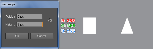
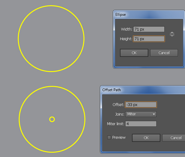
31. We will continue with the clock icon. Pick the Rectangle Tool (M) and create a 6 by 8px rectangle (R=255, G=255, B=255). Select the top-right anchor point of the newly created rectangle and remove it. Then select the top-left anchor point and move it 3px to the right. We will get a triangle. Next pick the Ellipse Tool (L) and create a 71 by 71px ellipse. Make sure that the newly created ellipse is still selected and go to the Object > Path > Offset Path… Enter a -33px Offset and click OK. Now select the bigger ellipse created in this step, hold down the Shift, click on the triangle, release the Shift and then click on the bigger ellipse again (to fixed its position). Next open the Align palette (Window > Align), click on the Horizontal Align Center button and then click on the Vertical Align Top button.
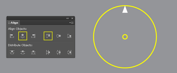
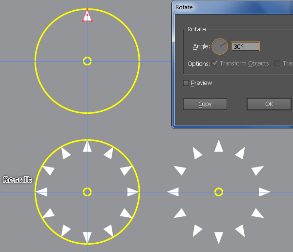
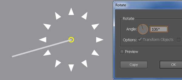
32. Drag a horizontal and vertical guide from the Rulers. Next select the bigger ellipse created in the step 31, hold down the Shift, click on two newly created guides, release the Shift and then click on the bigger ellipse again (to fixed its position). Then click on the Horizontal Align Center button from the Align palette and click on the Vertical Align Center button. Now select the triangle, pick the Rotate Tool (R), hold down the Alt key and click on the intersection point of the two newly created guides. In the Rotate dialog box, enter a 30 degrees Angle and click Copy, then press (Ctrl +D) ten times to get the results as shown in the third image. Finally select the bigger yellow ellipse and remove it.
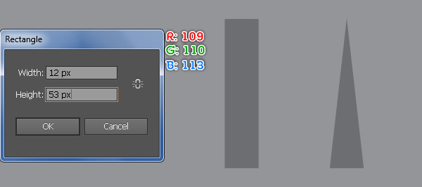
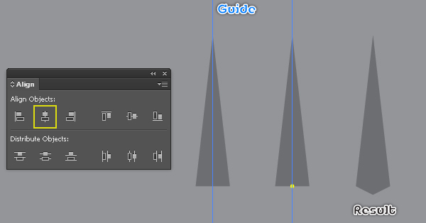
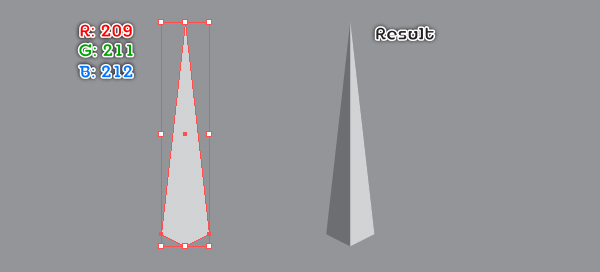
33. Next come the clock hands. First of all, we’ll create the minutes hand. With the Rectangle Tool (M) create a 12 by 53px rectangle (R=109, G=110, B=113). Select the top-right anchor point of the newly created rectangle and remove it. Then select the top-left anchor point and move it 6px to the right. We will get a triangle. Drag a vertical guide from the Ruler. Next select the triangle created in this step and the newly created vertical guide, then click on the Horizontal Align Center button from the Align palette. Focus on the fourth image, add an anchor point highlighted with yellow for the triangle and then move it 3px down. Reselect the shape created in this step and make a copy of it, then replace the existing color of the copy with R=209, G=211, B=212. Next select and remove the left anchor point of the newly created shape. Finally reselect and group the two shapes created in this step, then name this group “Minutes”.
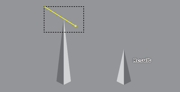
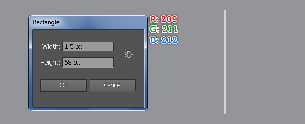
34. Select the group “Minutes” and make a copy of it, then place the copy to another position. Now focus on the newly created group, pick the Direct Selection Tool (A) and drag the mouse to the direction of the yellow arrow to create a marquee as shown in the first image. Next move the selected anchor points 26px down. Name this resulting group “Hour”. Next come the second hand. Pick the Rectangle Tool (M) and create a 1.5 by 68px rectangle (R=209, G=211, B=212), then name this rectangle “Second”.
35. Select the rectangle “Second” and go to the Object > Transform > Rotate… Enter a 106 degrees Angle and click OK, then place the resulting rectangle to the position as shown below. Next select the group “Hour” and rotate it an angle of about -120 degrees, then place the resulting group to the position like you see in the second image. Finally select the group “Minutes” and place it to the position as shown in the third image.


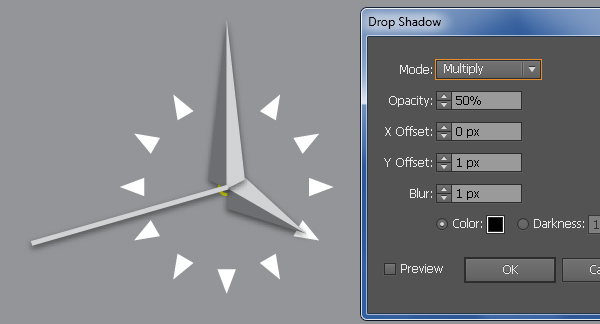
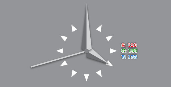
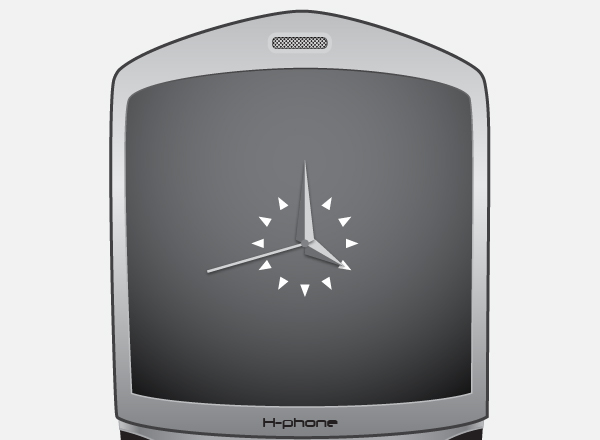
36. To give a more realistic look I’m going to be adding some shadows on the clock hands. Select the three clock hands and go to the Effect > Stylize > Drop Shadow… Follow the data as shown below and click OK. Next select the yellow ellipse, bring it to front (Ctrl +Shift +Right Square Bracket), then fill it with R=128, G=130, B=133 and remove the stroke color. Finally select and group (Ctrl +G) all objects created from beginning step 31 to this time, then place this group to the position as shown in the final image.
Create the Reflection on the Screen
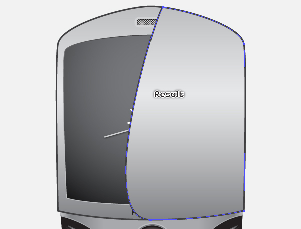
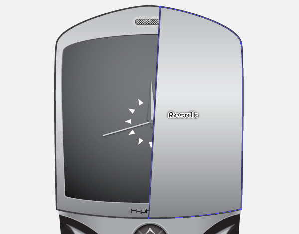
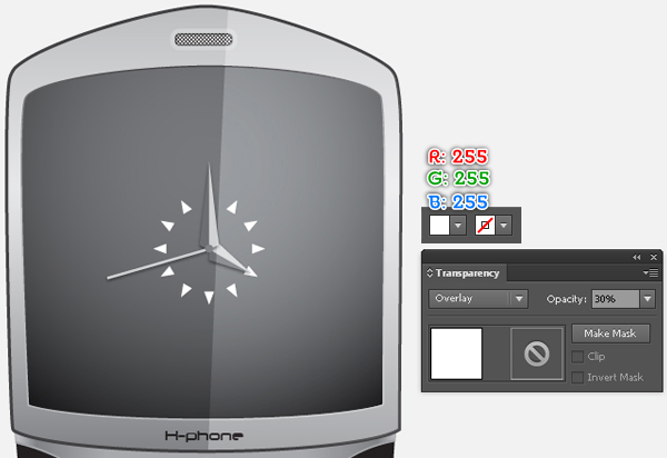
37. Select the upper shape created in the step 5 and make a copy of it, then bring the copy to front. With the Add Anchor Point Tool (+) add an anchor point highlighted with green for the newly created shape. Next select the three anchor points highlighted with red and remove them. Now focus on the third image, use the Convert Anchor Point Tool (Shift +C) to remove two left handles (make them length zero) of the top-left and the bottom-left anchor points of the newly created shape. Reselect the shape just edited in this step and replace the existing color of it with R=255, G=255, B=255. Then change the Blending Mode of the resulting shape to Overlay and lower the Opacity to 30%.
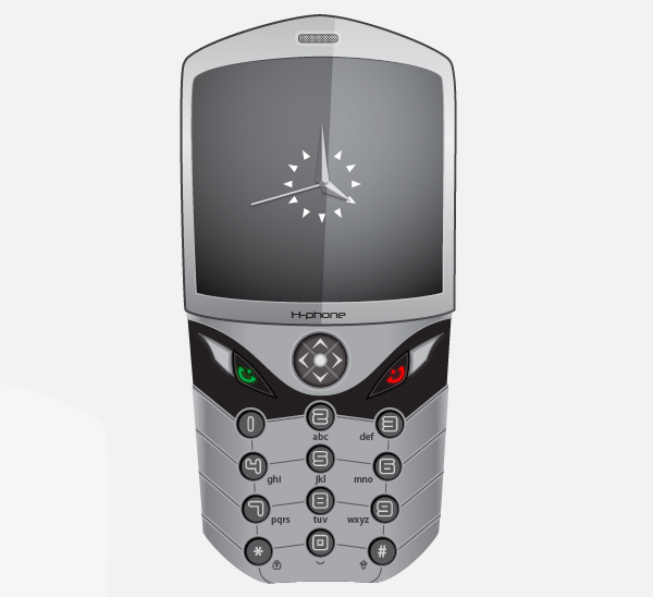
38. Select and group (Ctrl +G) all objects created from beginning step 2 to this time, then name this group “Cell_Phone”. The cell phone is ready and looks like this:
Create the Background
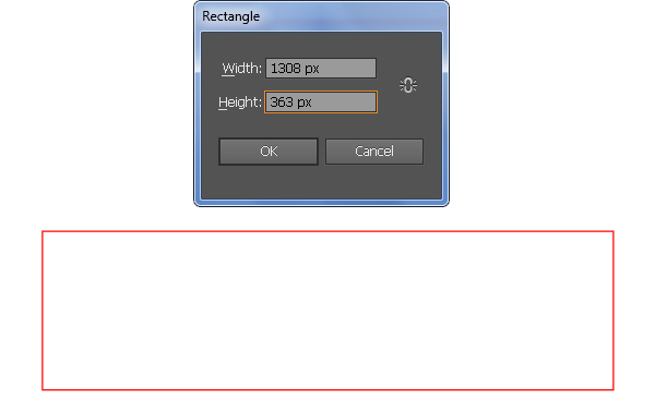
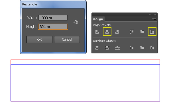
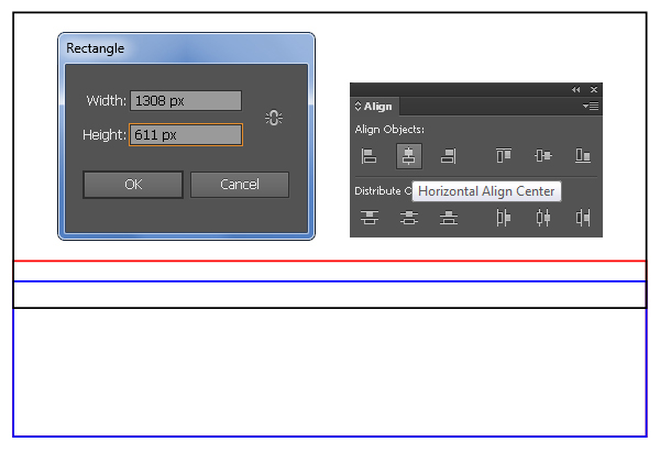
39. We’re done with the cell phone. It’s time for the background now. Pick the Rectangle Tool (M) and create two rectangles with dimensions: 1308 by 363px and 1308 by 321px. Next reselect the two newly created rectangles, open the Align palette (Window > Align), click on the Horizontal Align Center button and then click on the Vertical Align Bottom button. Continue working with the Rectangle Tool (M) create a 1308 by 611px rectangle, then place this rectangle to the position as shown in the third image below. Now select the blue rectangle created in this step, hold down the Shift, click on the newly created black rectangle, release the Shift and click on the blue rectangle again (to fixed its position), then click on the Horizontal Align Center button from Align palette.
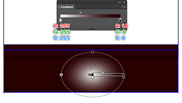
40. Fill the red rectangle with the radial gradient as shown below and then remove the stroke of it. Next select the group “Cell_Phone”, bring it to front and then place it to the position like you see in the second image. Finally select the black rectangle and fill it with the radial gradient as shown in the third image, then remove the stroke of it.
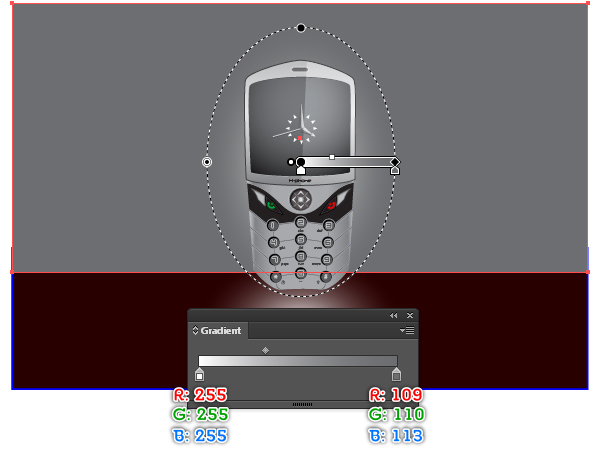
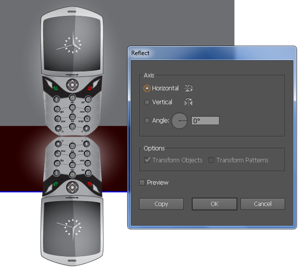
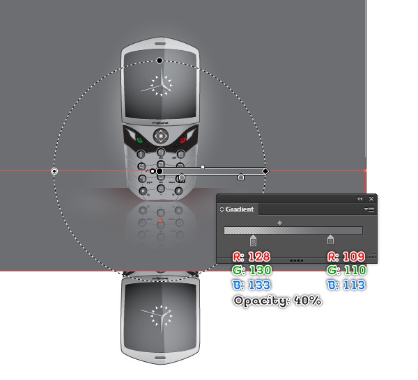
41. Select the group “Cell_Phone” and go to the Object > Transform > Reflect. Set the Axis to Horizontal and then click Copy. Drag the copy we have just created down to the position as shown below. Don’t forget to hold the Shift key on the keyboard for straight dragging. Now select the blue rectangle created in the step 39 and bring it to front (Ctrl +Shift +Right Square Bracket). Then fill it with the radial gradient like you see in the second image and remove the stroke of it.
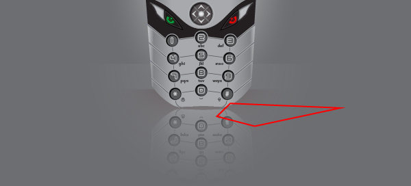
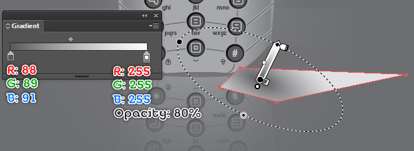
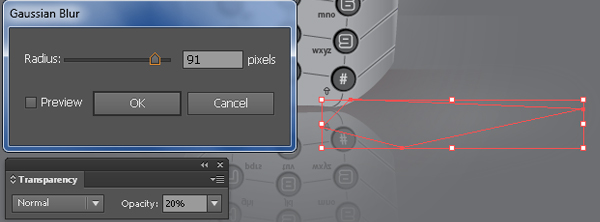
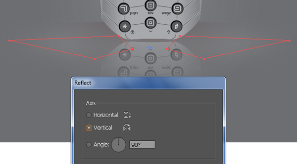
42. To add some details, first create a red object using the Pen Tool (P) like in the image below. Once your object is drawn, fill it with the radial gradient as shown in the second image, then remove the stroke of it. Next apply a 91px Gaussian Blur effect for the resulting shape and reduce the Opacity to 20%. Reselect the shape with blur effect applied in this step and make a copy (Ctrl +C, Ctrl +F) of it. Still having the newly created shape selected, reflect it vertically, then place it on the other side of the cell phone. Finally select the two shapes created in this step and hide them behind the cell phone.
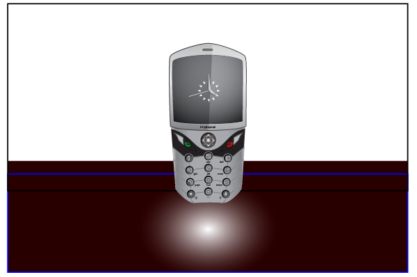
And We’re Done!