This Adobe Illustrator tutorial is the 4th part of a series of tutorials which help you learn how to create a Computer Peripheral Icons using some basic geometric shapes. This tutorial is about creating a Printer Icon.
You can read the first part of the tutorial here.
You can read the second part of the tutorial here.
You can read the third part of the tutorial here.
You can read the 4th part of the tutorial here.
If you have already read one the first three tutorials,
you can jump to the interesting part 🙂
Program: Adobe Illustrator CS6 – CC 2019
Difficulty: Beginner
Estimated Completion Time: 60 Minutes
How to Set Up a New Document
As we do with any new project, we’re going to start by setting up a custom document, by heading over to File > New (or by using the Control-N keyboard shortcut), which we will adjust as follows:
Number of Artboards: 2
Spacing: 32 px
Width: 64 px
Height: 64 px
Units: Pixels
And from the Advanced tab:
Color Mode: RGB
Raster Effects: Screen (72ppi)
Preview Mode: Default
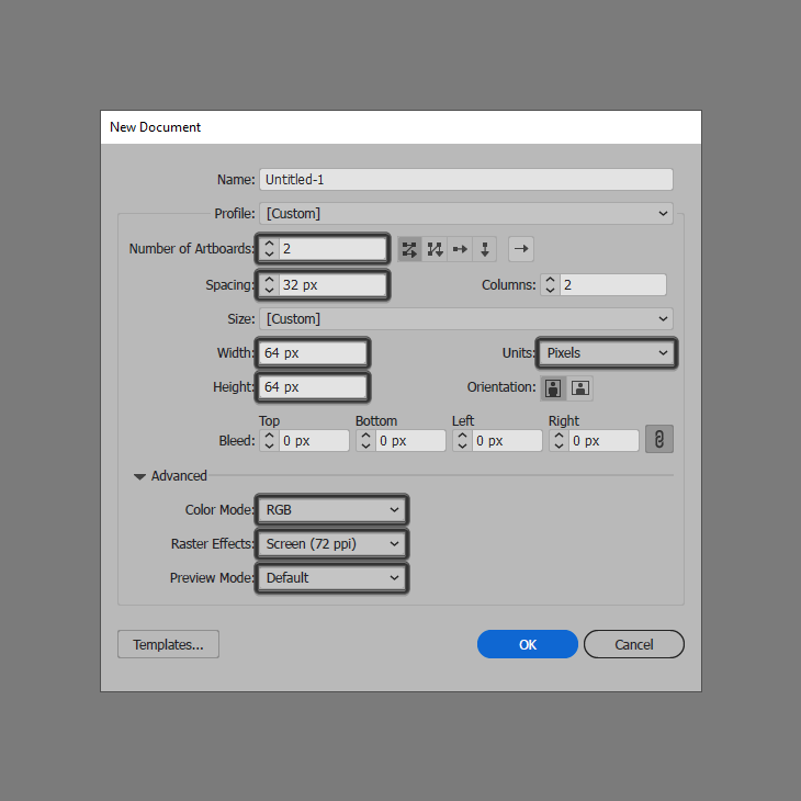
Quick tip: most of the indicated settings can be automatically triggered if you set the document’s Profile to Web, the only one that you’ll have to manually adjust being the Artboard’s Size (Width and Height).
How to Set Up the Layers
As soon as we’ve finished setting up the project file, we’re going to want to separate our icons from the reference grids using a couple of layers in order to streamline the workflow.
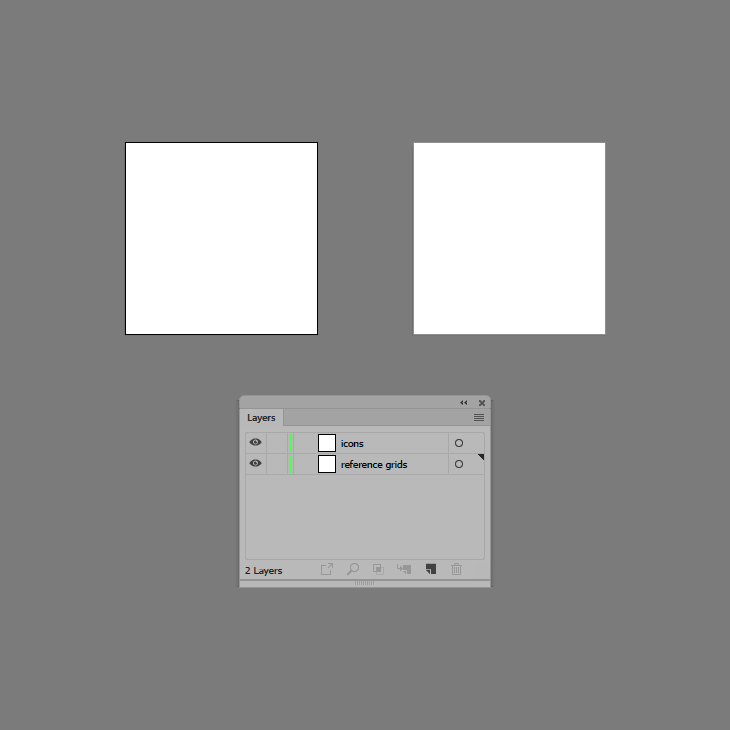
That being said, open up the Layers panel, and create a new one making sure to rename them both afterwards using simple descriptive labels.
How to Create the Reference Grids
Once we’re done creating the layers, we’re going to quickly go through the process of setting up the reference grids, which will help us achieve size consistency across our two icons.
Step 1
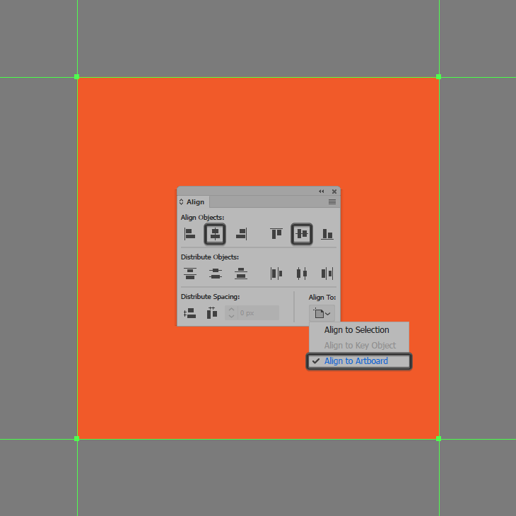
Create the main shape for the reference grid using a 64 x 64 px square, which we will color using #F15A24 and then position to the center of the first Artboard.
Step 2
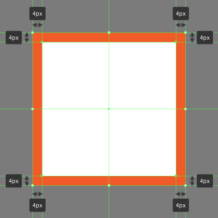
Add the active drawing area using a smaller 56 x 56 px square, which we will color using white (#FFFFFF) and then center align to the shape from the previous step, which should give us an all-around 4 px protective padding. Once you’re done, make sure you select and group the two together using the Control-G keyboard shortcut.
Step 3
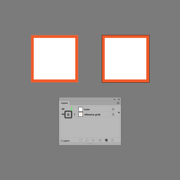
Populate the second Artboard using a copy (Control-C) of the reference grid that we’ve just finished working on, which we will paste in place using the Control-F keyboard shortcut. Once you’re done, make sure you lock the current layer before moving on to the next step.
How to Create the USB Stick Icon
Assuming you’ve finished setting up the reference grids, we’re going to position ourselves onto the first Artboard, and then zoom in on its reference grid so that we can have a better view of the shapes that we’re going to be using to gradually build our first icon.
Step 1
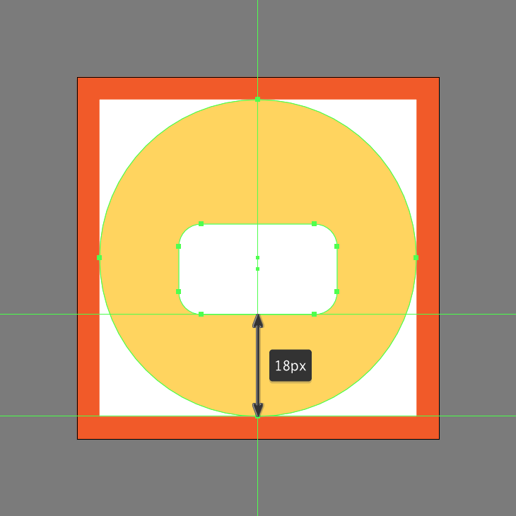
Start by creating the background using a 56 x 56 px circle, which we will color using #FFD55F and then center align to the underlying Artboard using the Align panel’s Horizontal and Vertical Align Center options.
Step 2
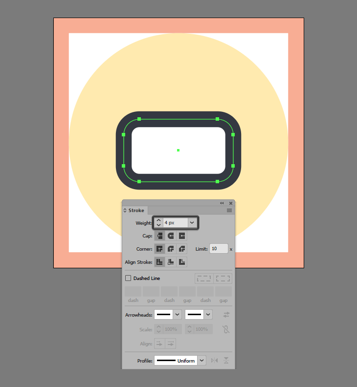
Add the main shape for the printer’s body using a 28 x 16 px rounded rectangle with a 4 px Corner Radius, which we will color using white (#FFFFFF) and then center align to the larger circle, positioning it at a distance of 18 px from its bottom anchor point.
Step 3
Give the shape that we’ve just created an outline using the Stroke method, by creating a copy of it (Control-C) which we will paste in front (Control-F) and then adjust by first changing its color to #31353F and then setting its Weight to 4 px. Once you’re done, make sure you select and group the two shapes together using the Control-G keyboard shortcut.
Step 4
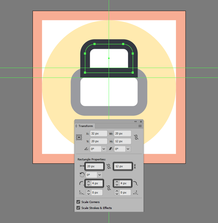
Create the feeding tray using a 20 x 12 px rectangle (#FFFFFF), which we will adjust by opening up the Transform panel, and then setting the Radius of its top corners to 4 px from within the Rectangle Properties. Give the resulting shape a 4 px thick outline (#31353F) and then position the two on top of the printer’s body so that their outlines perfectly overlap.
Step 5
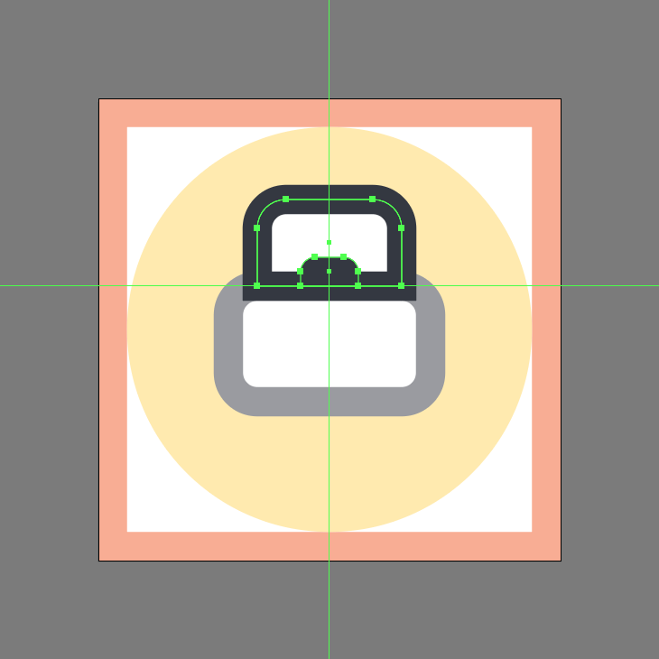
Add the little insertion segment using an 8 x 4 px rectangle (#31353F), which we will adjust by setting the Radius of its top corners to 2 px, and then position the resulting shape to the center of the tray’s bottom edge. Once you have the shape in place, select and group all of the tray’s composing shapes using the Control-G keyboard shortcut.
Step 6
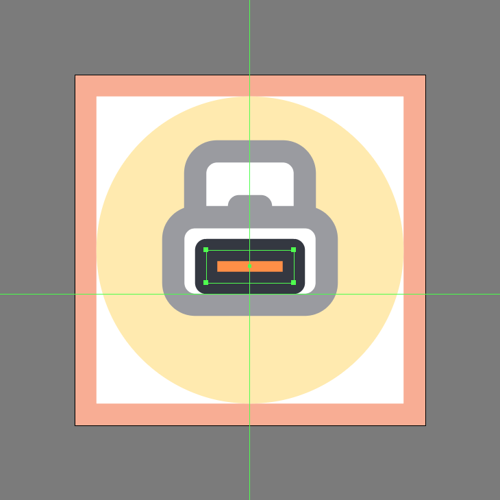
Create the printer’s inner section using a 16 x 6 px rectangle (#FF9045) with a 4 px thick outline (#31353F) with the Corner set to Round Join, and then group (Control-G) and position the two as seen in the reference image.
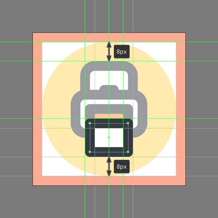
Step 7
Add the paper segment using a 16 x 12 px rectangle (#FFFFFF) with a 4 px thick outline (#31353F) with a Round Join, which we will position so that they overlap the lower edge of the printer’s inner section.
Step 8
Finish off the icon by adding the little text line using a 6 px wide 2 px thick Stroke (#31353F) with a Round Cap, which we will position as seen in the reference image. Once you have the shape in place, don’t forget to select and group (Control-G) all of the paper’s composing shapes, doing the same for the entire printer and icon afterwards.
Awesome Job!
As always, I really hope you had fun working on the project, and most importantly managed to learn something new and useful during the process.