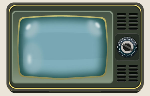
In this tutorial you’ll learn how to create a vintage television with the use of some basic techniques in Adobe Illustrator. You will learn lots of useful illustrator tricks to speed up drawing of a television face along with some other parts of the television. Hope you will enjoy this tutorial and maybe even discover some new methods along the way. Let’s begin!

Create a New Document
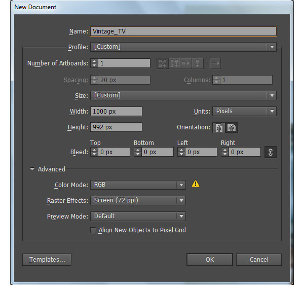
1. Launch Illustrator and then press (Ctrl + N) to create a New document. Select Pixels from the Units drop-down menu, enter 1000 in the width box and 992 in the height box then click on the Advanced button. Select RGB, Screen (72ppi) and make sure that the Align New Objects to Pixel Grid box is unchecked before you click OK.
Create the Basic Frame.
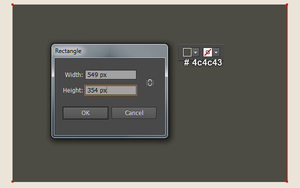
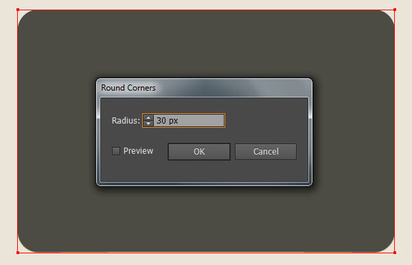
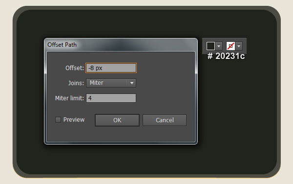
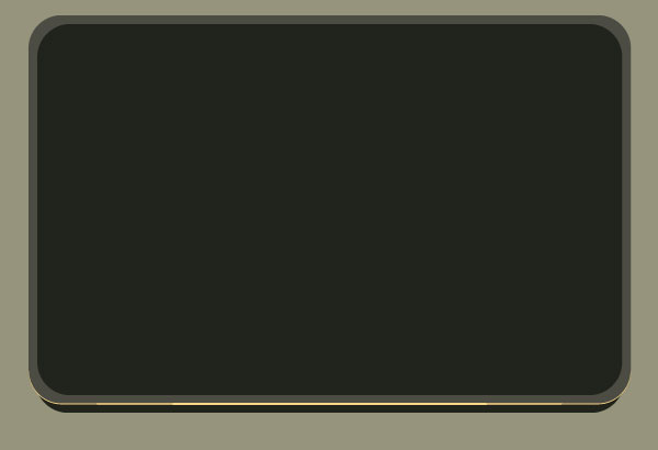
2. Pick the Rectangle Tool (M) and create a 549 by 354px very dark grayish yellow rectangle (# 4c4c43). Still having the newly created rectangle selected and go to the Effect > Stylize > Round Corners… Enter a 30px Radius and click OK. Keep the resulting rectangle selected and go to the Object > Path > Offset Path… Enter a -8px Offset and click OK. Then replace the existing fill color of the newly created rectangle with very dark green (# 20231c).
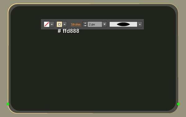
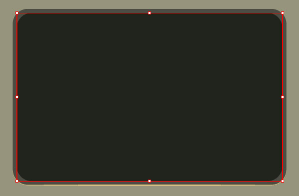
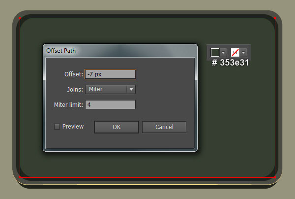
3. Select the bigger rectangle created in the step 2 and make a copy (Ctrl +C, Ctrl +F) of it. Keep the copy selected, swap the fill and stroke colors by clicking the bent double-headed arrow next to the Fill and Stroke color swatches in the Toolbox. Change the stroke weight of the resulting object to 2px and replace the existing stroke color with very light orange (# ffd888). Then apply the Width Profile 1 for this object. Focus on the first image, select two anchor points highlighted with green and click on the “Cut path at selected anchor points” icon from the Properties bar. This make the very light orange object becomes two paths. Select and remove the upper path. Now select the smaller rectangle created in the step 2 and make a copy (Ctrl +C, Ctrl +F) of it. Move the copy 16px down and then send it to back (Ctrl +Shift +Left Square Bracket). Next select the smaller rectangle created in the step 2 again and go to the Object > Path > Offset Path… Enter a -7px Offset and click OK. Then replace the existing fill color of the resulting rectangle with very dark grayish green (# 353e31).
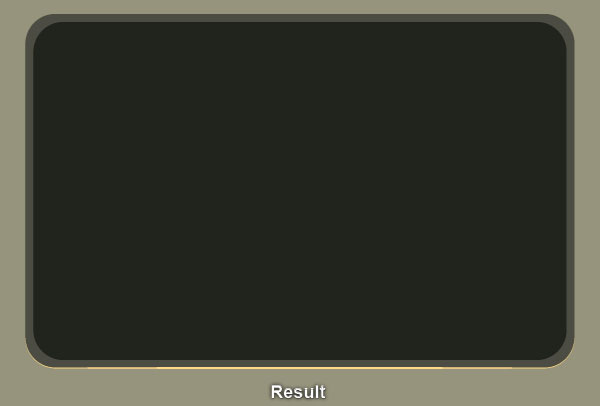
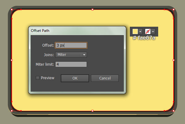
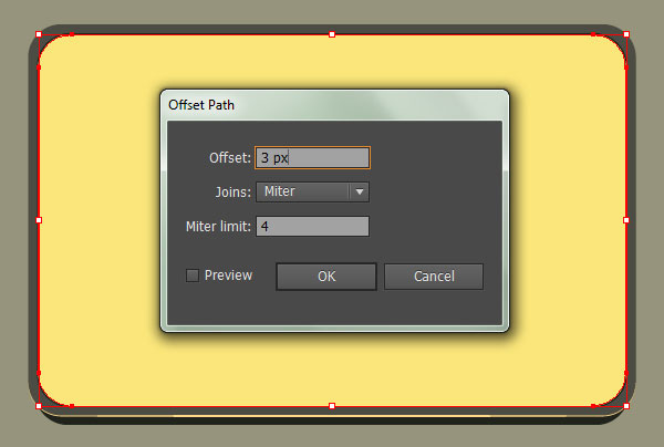
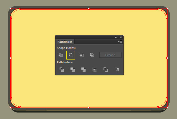
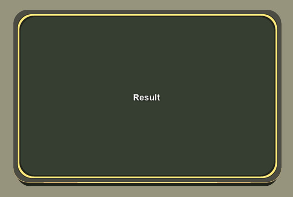
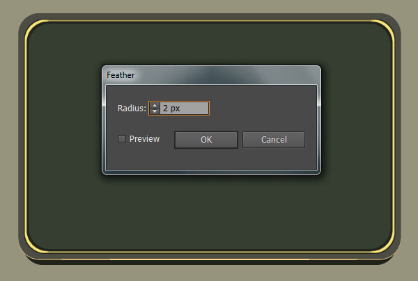
4. Select the last rectangle created in the step 3 and go to the Object > Path > Offset Path… Enter a 3px Offset and click OK, then replace the existing fill color of the newly created rectangle with soft yellow (# fae67a). Keep the resulting rectangle selected and open the Offset Path dialog box again. Enter a 3px Offset and click OK. Now reselect the two soft yellow rectangles, then open the Pathfinder panel (Window > Pathfinder) and click on the Minus Front button. Finally apply a 2px Feather effect for the resulting compound path.
Create the Display.
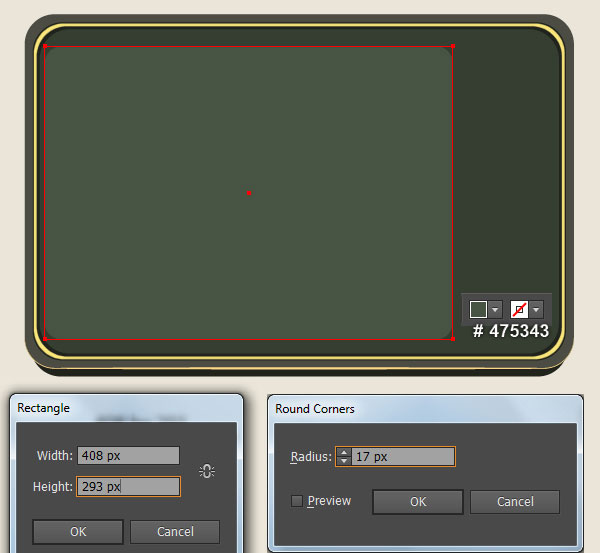
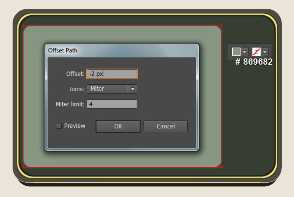
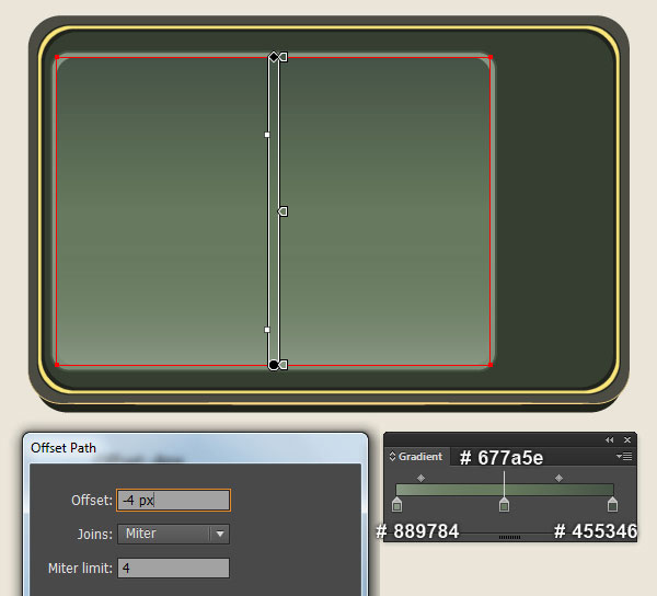
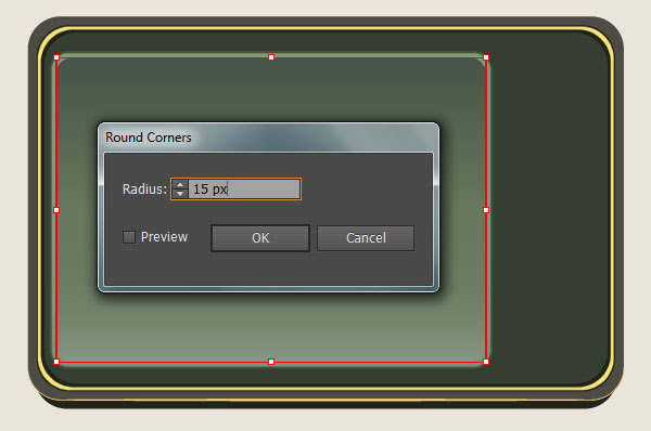
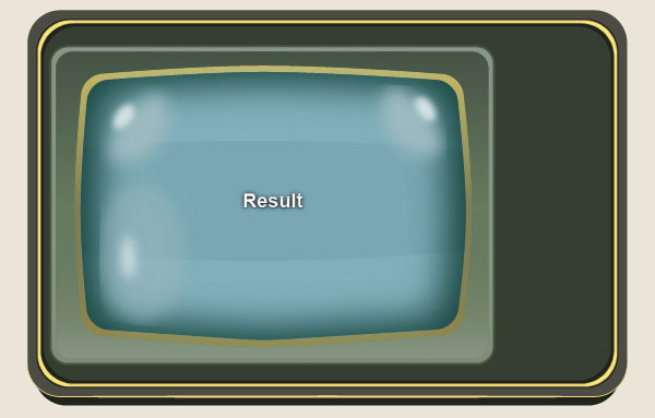
5. We will now proceed with the display. Pick the Rectangle Tool (M) and create a 408 by 293px very dark grayish green rectangle (# 475343), then place it to the position like you see in the first image. Still having the newly created rectangle selected and go to the Effect > Stylize > Round Corners… Enter a 17px Radius and click OK. Keep the resulting rectangle selected and go to the Object > Path > Offset Path… Enter a -2px Offset and click OK, then replace the existing fill color of the newly created rectangle with dark grayish lime green (# 869682). Make sure that the resulting rectangle is still selected and open the Offset Path dialog box. Enter a -4px Offset and click OK, then replace the existing fill color of the newly created rectangle with the linear gradient as shown in the next to last image. Keep the resulting rectangle selected, open the Appearance panel (Window > Appearance) and click on the Round Corners section. In the Round Corners dialog box, enter a 15px Radius and click OK.
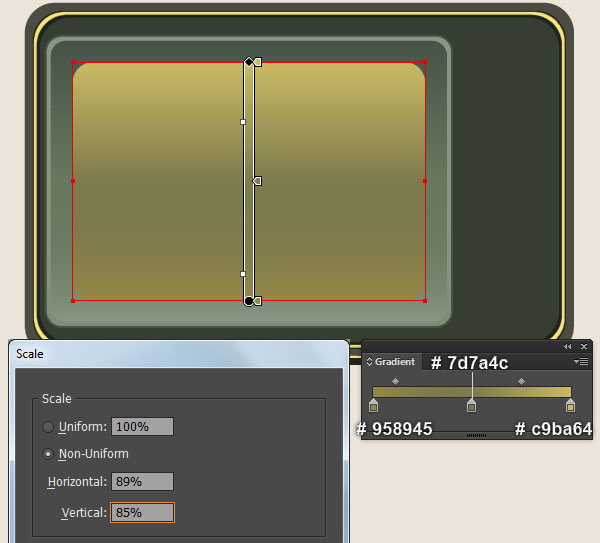
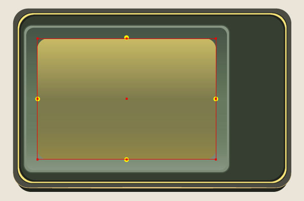
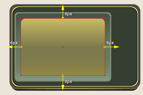
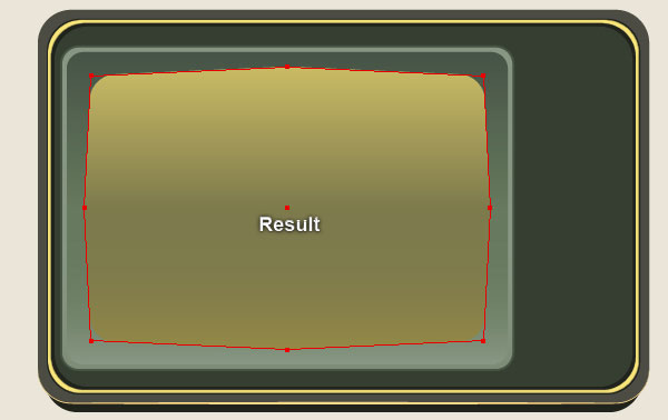
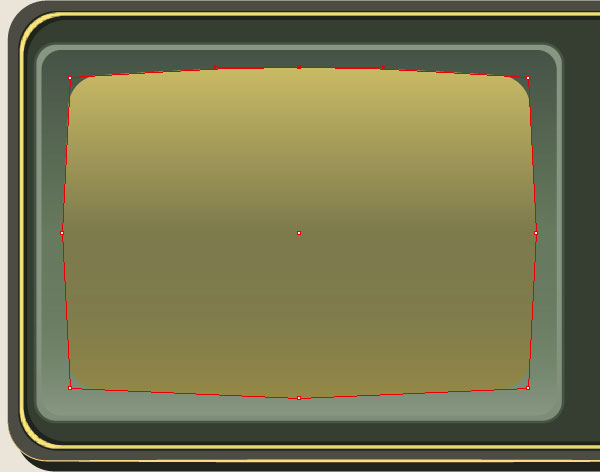
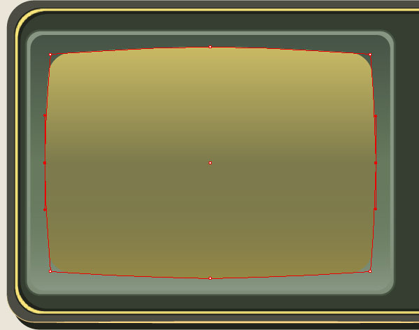
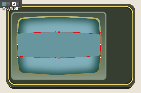
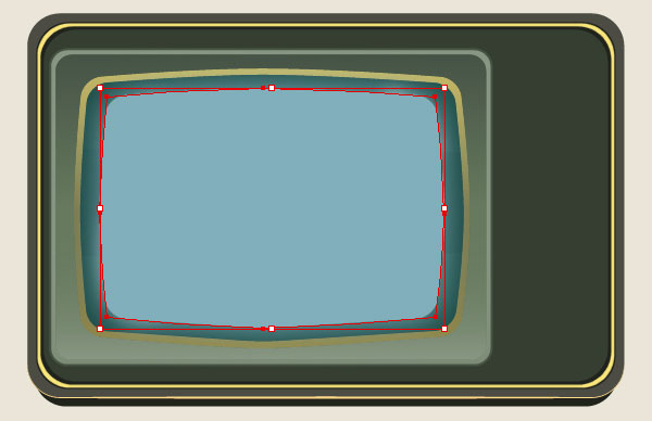
6. Select the last rectangle created in the step 5 and go to the Object > Transform > Scale… Check the Non-Uniform, enter a 89% in the Horizontal box and 85% in the Vertical box, then click Copy. Replace the existing fill color of the newly created rectangle with new linear gradinet as shown in the first image. Focus on the second image, pick the Add Anchor Point Tool (+) and add four new anchor points at the points highlighted with yellow. Now pick the Direct Selection Tool (A), select the top-middle anchor point you just added and move it 8px up. Next select the bottom-middle anchor point and move it 8px down. Keep working with the Direct Selection Tool (A), select the middle-left anchor point and move it 6px to the left. Finally select the middle-right and then move it 6px to the right.
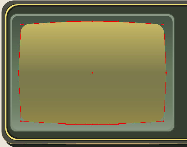
7. Pick the Rectangle Tool (M) and create a 200 by 670px black rectangle. Pick the Convert Anchor Point Tool (Shift +C), click on the top-middle anchor point you just moved in the step 6, then hold mouse and drag it to the right while holding Shift. Next click on the bottom-middle anchor point, hold mouse and drag it to the left. Keep working with the Convert Anchor Point Tool (Shift +C), click on the middle-left anchor point, hold mouse and drag it up. Don’t forget to hold the Shift key on the keyboard for straight dragging. Finally click on the middle-right anchor point, then hold mouse and drag it down.

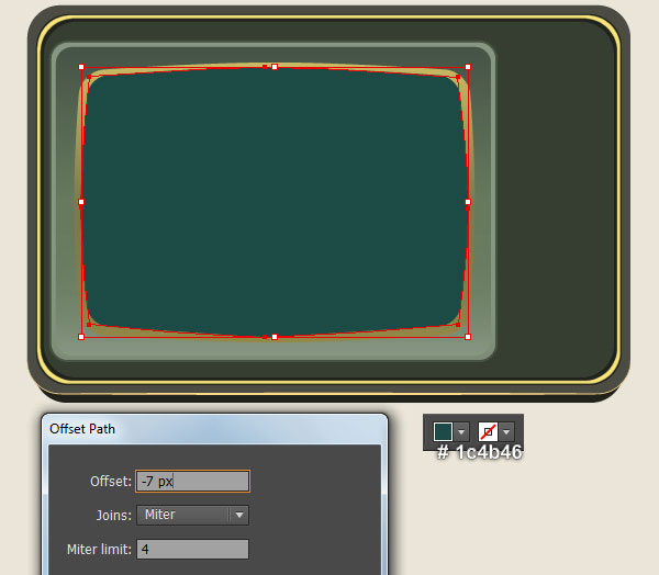
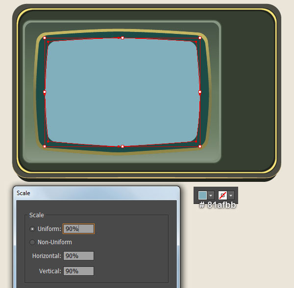
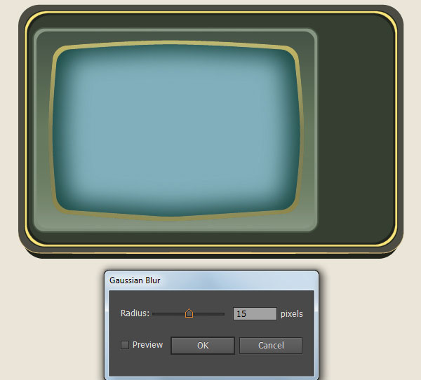
8. Select the shape created in the step 7 and go to the Object > Path > Offset Path… Enter a -7px Offset and click OK, then replace the existing fill color of the newly created shape with very dark cyan (# 1c4b46). Still having the resulting shape selected and go to the Object > Transform > Scale… Check the Uniform, enter a 90% in the Scale box and click Copy. Then replace the existing fill color of the newly created shape with slightly cyan (# 81afbb). Keep the resulting shape selected and apply a 15px Gaussian Blur effect for it.
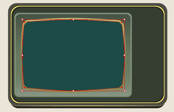
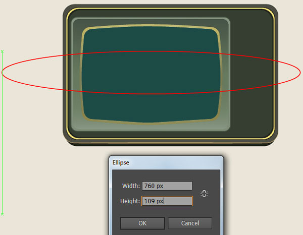
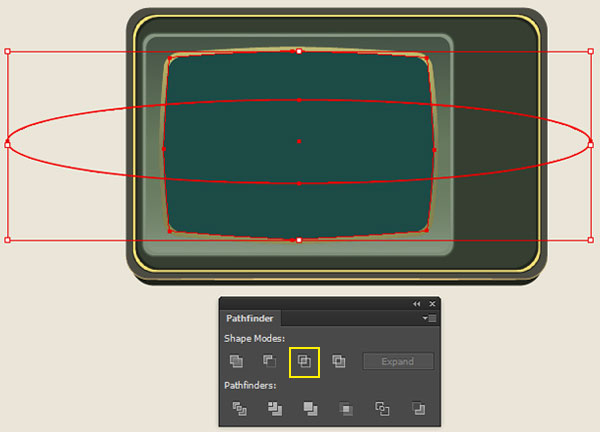
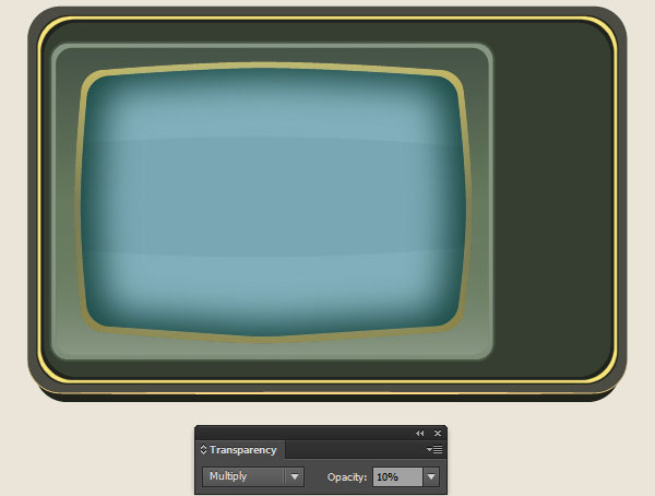
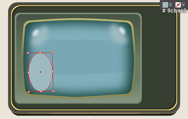
9. Select the first shape created in the step 8 and make a copy (Ctrl +C, Ctrl +F) of it, then bring the copy to front (Ctrl +Shift +Right Square Bracket). With the help of the Ellipse Tool (L), create a 760 by 109px red ellipse, then place it to the position like you see in the second image. Keep this ellipse selected, hold down the Shift and click on the first shape created in this step. Then open the Pathfinder panel (Window > Pathfinder) and click on the Intersect button. Remove the stroke of the newly created object and then fill it with dark cyan (# 67969f). Finally change the Blending Mode of the resulting shape to Multiply and reduce its Opacity to 10%.
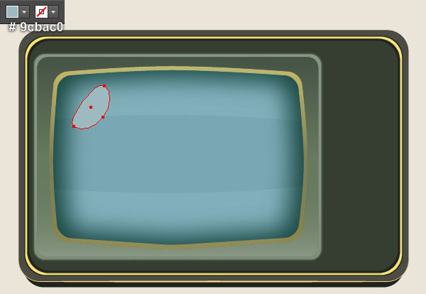
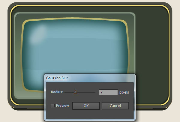
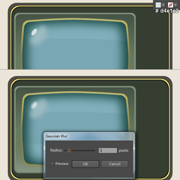
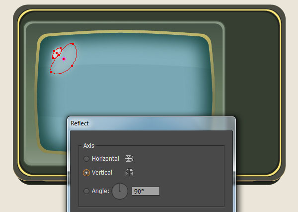
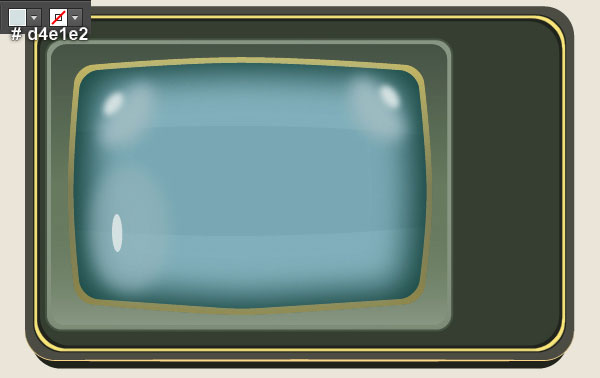
10. Pick the Pen Tool (P) and create a grayish cyan shape (# 9cbac0) as shown in the first image. Once your shape is drawn, reselect it and apply a 7px Gaussian Blur effect for this shape. With the Ellipse Tool (L), create a light grayish cyan ellipse (# d4e1e2) like you see in the third image. Then apply a 3px Gaussian Blur effect for the newly created ellipse. Now select the two shapes created in this step and go to the Object > Transform > Reflect… Check the Vertical and click Copy. Drag the copies we have just created to the right. Don’t forget to hold the Shift key on the keyboard for straight dragging.
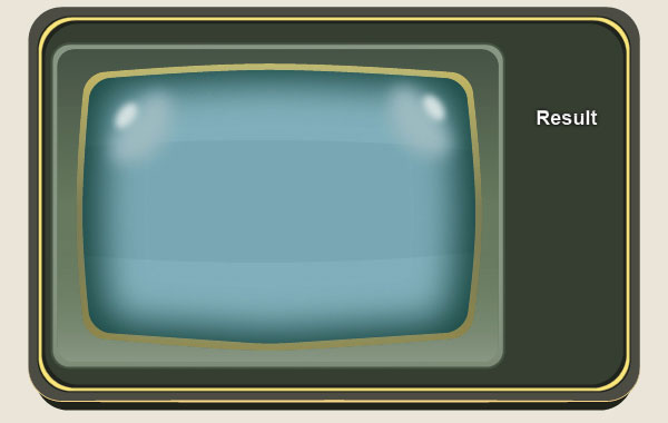
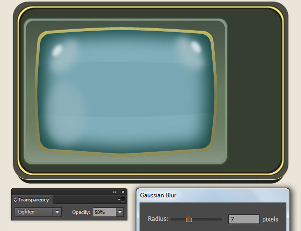
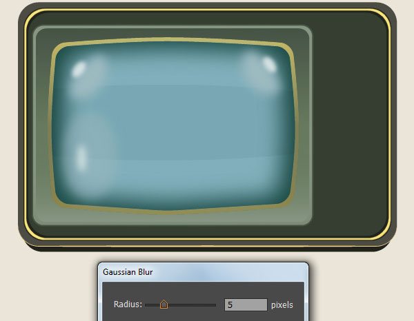
11. With the help of the Ellipse Tool (L), create a grayish cyan ellipse (# 9cbac0) and place it to the position like you see in the first image. Apply a 7px Gaussian Blur effect for the newly created ellipse, then change the Blending Mode to Lighten and reduce its Opacity to 50%. Keep working with the Ellipse Tool (L), create a light grayish cyan ellipse (# d4e1e2) and place it to the position as shown in the third image. Then apply a 5px Gaussian Blur effect for the newly created ellipse. Finally select and group (Ctrl +G) all objects created from beginning step 10 to this time.
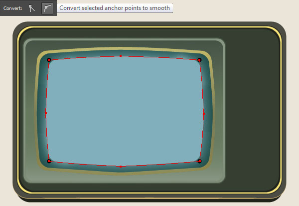
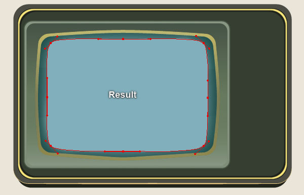
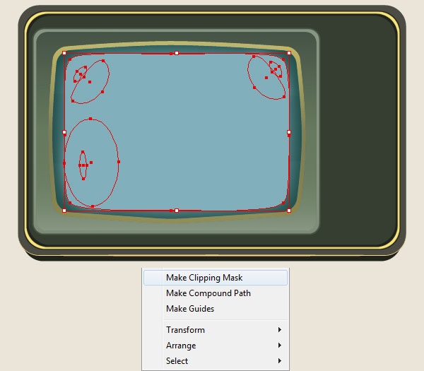
12. Select the shape with blur effect applied in the step 8 and make a copy (Ctrl +C, Ctrl +F) of it, then bring the copy to front (Ctrl +Shift +Right Square Bracket). Keep this copy selected, open the Appearance panel (Window > Appearance) and remove the Gaussian Blur section. Focus on the second image, select four anchor points highlighted with black and click on the “Convert selected anchor point to smooth” icon from the Properties bar. Reselect the resulting shape and go to the Object > Expand Appearance. The resulting shape should look like the third image below. Make sure that this shape is still selected, hold down the Shift and click on the group created in the step 11. Right-click on the artboard and then select the Make Clipping Mask section from the drop-down menu.
Create the Channel Selector Button.
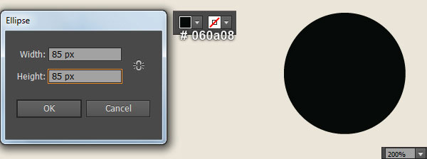
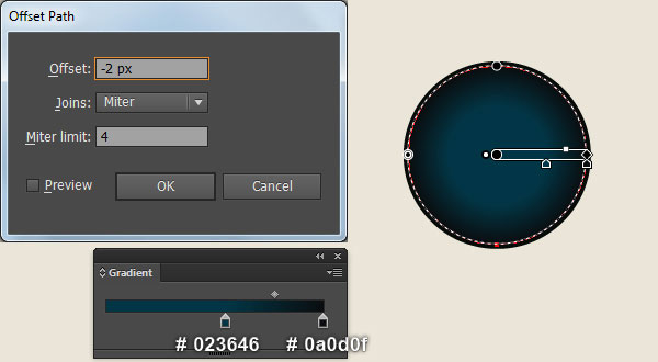
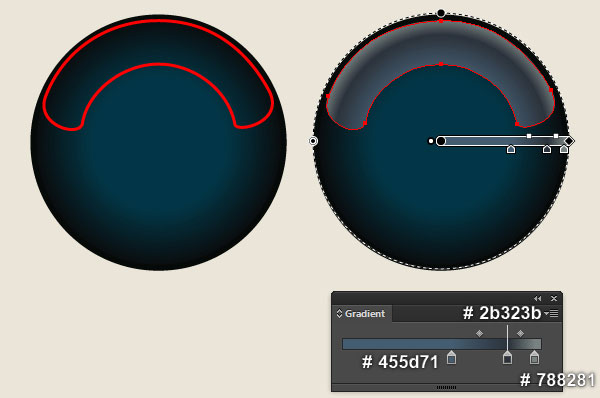
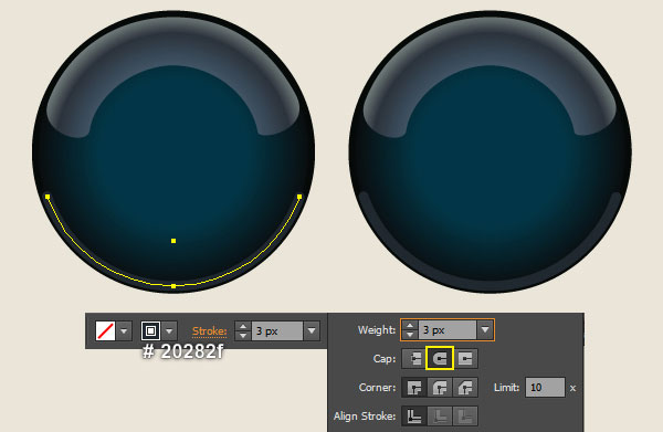
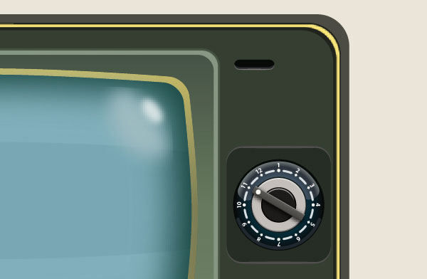
13. Pick the Ellipse Tool (L) and create a 85 by 85px very dark green ellipse (# 060a08). Keep the newly created ellipse selected and go to the Object > Path > Offset Path… Enter a -2px Offset and click OK, then replace the existing fill color of the resulting ellipse with the radial gradient as shown in the second image. With the help of the Pen Tool (P) and the Gradient Tool (G), create a shape like you see in the third and the fourth image. Next focus on the last two images, draw a curved path with the Pen Tool (P) and give it a 3px very dark blue stroke (# 20282f) for the moment. Still having the newly created path selected, open the Stroke panel (Window > Stroke) and click on the Round Cap icon.
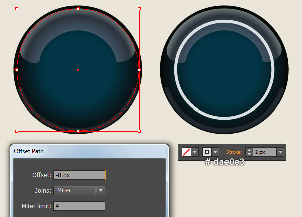
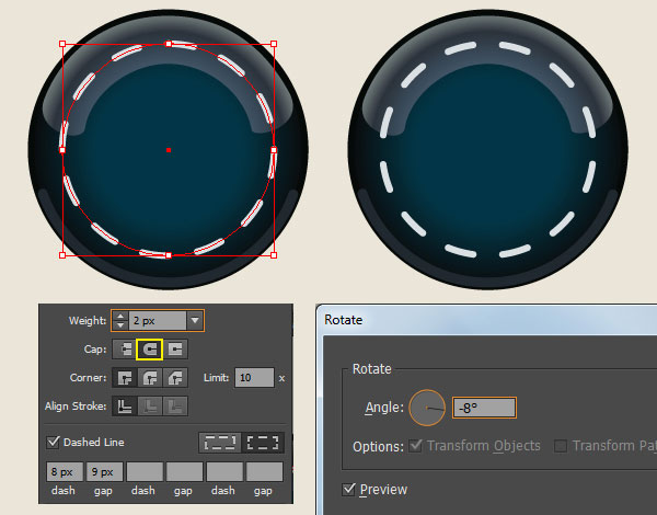
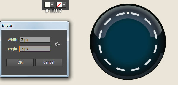
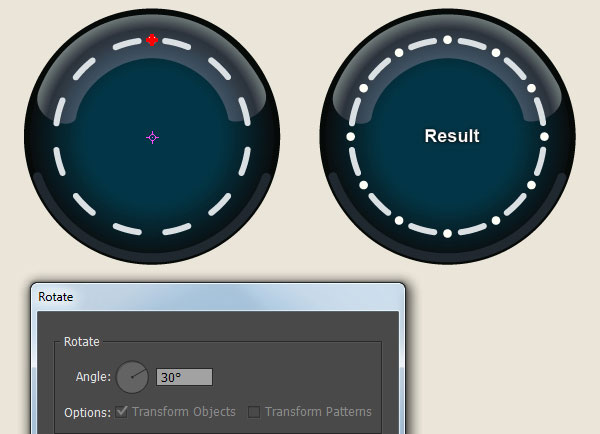
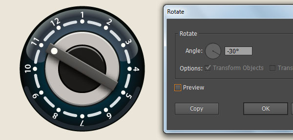
14. Select the ellipse as shown in the first image and go to the Object > Path > Offset Path… Enter a -8px Offset and click OK. Keep the newly created ellipse selected, swap the fill and stroke colors by clicking the bent double-headed arrow next to the Fill and Stroke color swatches in the Toolbox. Replace the existing stroke color of the resulting ellipse with light grayish blue (# dae0e3) and change the stroke weight to 2px. Still having the resulting ellipse selected, open the Stroke panel (Window > Stroke) and click on the Round Cap icon. Then check the Dashed Line box. Enter 8px in the dash box and 9px in the gap box. Make sure that the resulting ellipse is still selected and go to the Object > Transfrom > Rotate… Enter a -8 degrees Angle and click OK. Now pick the Ellipse Tool (L) and create a 3 by 3px very pale yellow ellipse (# fffff7), then place it to the position as shown in the fifth image. Reselect the newly created ellipse, pick the Rotate Tool (R), then hold down the Alt and click on the center of the first ellipse created in this step. In the Rotate dialog box, enter a 30 degrees Angle and click Copy. Repeat this by pressing (Ctrl +D). Do this until you get the results as shown in the last image.
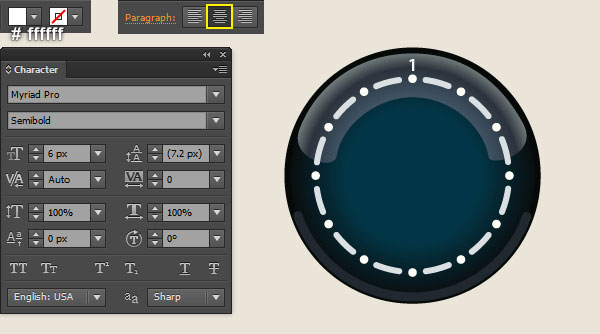
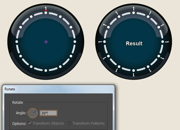
15. Open the Character panel (Window > Type > Character), select the Myriad Pro font, make it Semibold, and set the size to 6px. Now pick the Type Tool (T), simply click on your artboard. Then type the number “1” and set its color to white (# ffffff). Keep this number selected and open the Paragraph panel (Window > Type > Paragraph) and click on the Align Center icon. Still having the number “1” selected, pick the Rotate Tool (R), hold down the Alt and click on the center of the first ellipse created in the step 14. In the Rotate dialog box, enter a 30 degrees Angle and click Copy. Repeat this by pressing (Ctrl +D). Do this until you get the results as shown in the third image. Next use the Type Tool (T) to change eleven newly created numbers “1” to the correct numbers like you see in the last image.
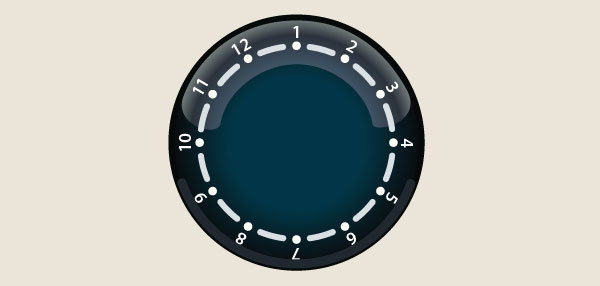
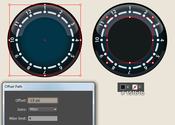
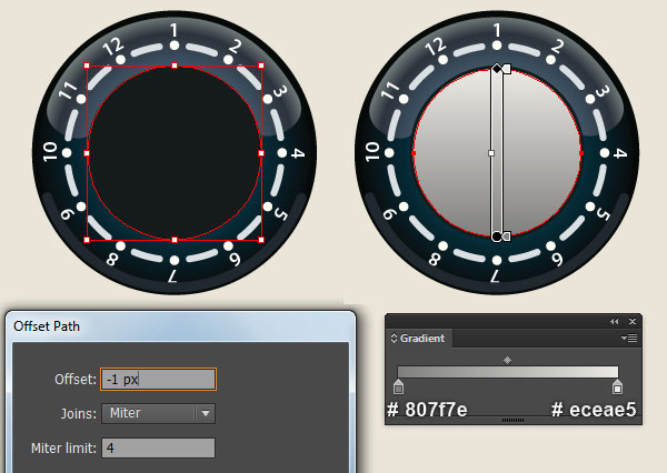
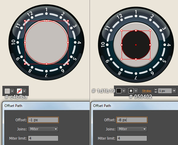
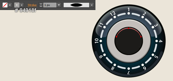
16. Select the ellipse as shown in the first image and go to the Object > Path > Offset Path… Enter a -15px Offset and click OK. Then replace the existing fill color of the newly created ellipse with very dark cyan (# 151b1b). Keep the resulting ellipse selected and go to the Object > Path > Offset Path… Enter a -1px Offset and click OK, then replace the existing fill color of the newly created ellipse with the linear gradient as shown in the fourth image. Still having the resulting ellipse selected and open the Offset Path dialog box. Enter a -1px Offset and click OK, then replace the existing fill color of the newly created ellipse with grayish orange (# c4bfba). Make sure that the resulting ellipse is still selected and open the Offset Path dialog box again. Enter a -8px Offset and click OK. Replace the existing fill color of the newly created ellipse with very dark orange (# 1d1b19) and then add a 1px very dark orange stroke (# 050402) for the resulting ellipse. Focus on the last image, draw a curved path with the Pen Tool (P) and give it a 1px dark grayish orange stroke (# 94918f) for the moment. Finally apply the Width Profile 1 for the resulting path.
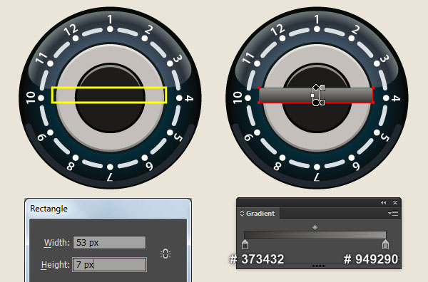
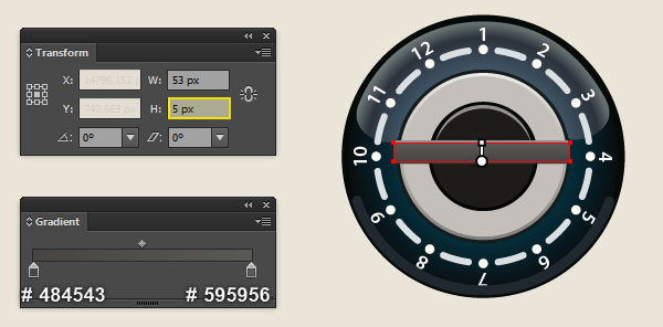
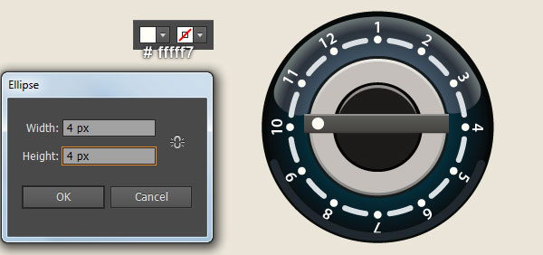
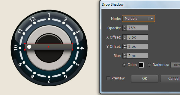
17. With the help of the Rectangle Tool (M) and the Gradient Tool (G), create a 53 by 7px rectangle as shown in the first and the second image. Keep the newly created rectangle selected and make a copy (Ctrl +C, Ctrl +F) of it. Still having the copy selected, open the Transform panel (Window > Transform) and change H to 5px. Then replace the existing fill color of the resulting rectangle with new linear gradient as shown in the third image. Next with the Ellipse Tool (L), create a 4 by 4px white ellipse (# fffff7) and place it to the position like you see in the fourth image. Now select and group (Ctrl +G) all three objects created in this step. Make sure that the newly created group is still selected and go to the Effect > Stylize > Drop Shadow… Follow the data as shown in the next to last image and click OK. Keep the resulting group selected and go to the Object > Transform > Rotate… Enter a -30 degrees Angle and click OK.
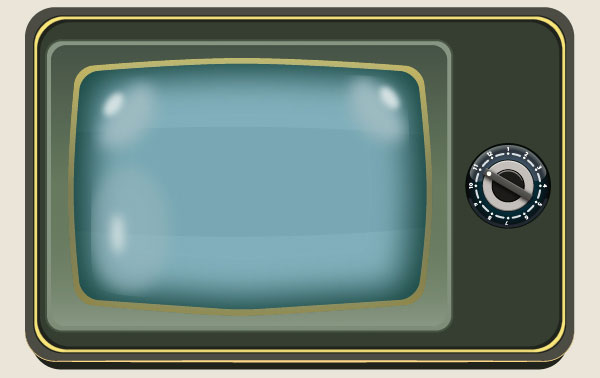
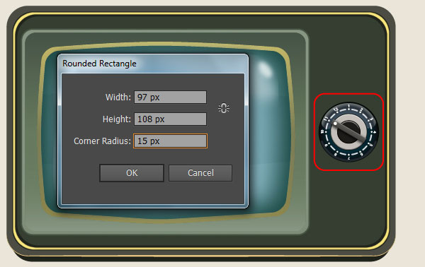
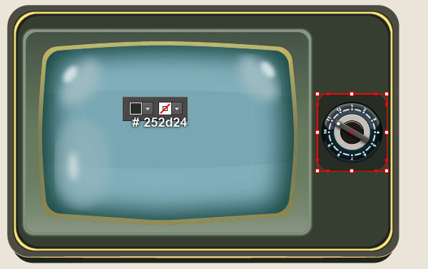
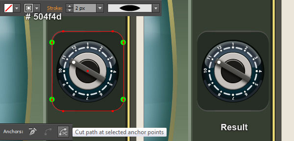
18. Before you continue, select and group (Ctrl +G) all objects created from beginning step 13 to this time, then place the newly created group to the position as shown in the first image. With the Rounded Rectangle Tool, create a red rounded rectangle and place it to the position like you see in the second image. Remove the stroke of the newly created rectangle and fill this object with very dark lime green (# 252d24). Keep the resulting rectangle selected and make a copy (Ctrl +C, Ctrl +F) of it. Remove the fill color of the copy and add a 2px very dark grayish orange stroke (# 504f4d) for this rectangle. Then apply the Width Profile 1 for the resulting rectangle. Now focus on the next to last image, select four anchor points highlighted with green and click on the “Cut path at selected anchor points” icon from the Properties bar. This make the very dark grayish orange rectangle becomes four paths. Select and remove the two vertical paths.
Create the Speaker.
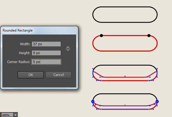
19. Now we’re going to make the speaker. With the Rounded Rectangle Tool, create a black rounded rectangle as shown in the first image. Make a copy (Ctrl +C, Ctrl +F) of the newly created rectangle and then replace the existing stroke color of the copy with red. Focus on the second image, select the right anchor point highlighted with black, move it 2px to the left and 7px down. Next select the left anchor point highlighted with black, move it 2px to the right and 7px down. Now focus on the last image, pick the Convert Anchor Point Tool (Shift +C), click on the upper handle of the left anchor point highlighted with blue, then hold mouse and drag it to the right and down. Next click on the upper handle of the right anchor point highlighted with blue, hold mouse and drag it to the left and down.
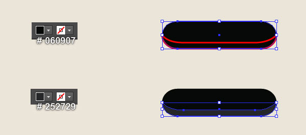
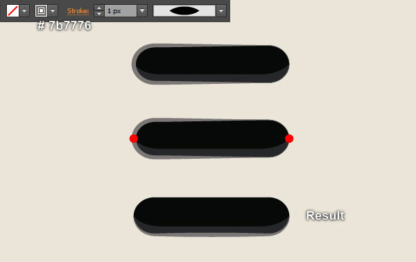
20. Select the black rounded rectangle created in the step 19, remove its stroke and fill this object with very dark green (# 060907). Next select the red object, remove its stroke and fill this object with very dark blue (# 252729). Now select the rounded rectangle you just filled with very dark green color and make a copy (Ctrl +C, Ctrl +F) of it, then bring the copy to front (Ctrl +Shift +Right Square Bracket). Keep this copy selected, swap the fill and stroke colors by clicking the bent double-headed arrow next to the Fill and Stroke color swatches in the Toolbox. Replace the existing stroke color of the resulting object with dark grayish red (# 7b7776) and apply the Width Profile 1 for it. Now focus on the next to last image, select the two anchor points highlighted with red and click on the “Cut path at selected anchor points” icon from the Properties bar. This make the dark grayish red object becomes two paths. Select and remove the upper path. Finally select and group (Ctrl +G) all three objects created from beginning step 19 to this time, then name it “Speaker“.
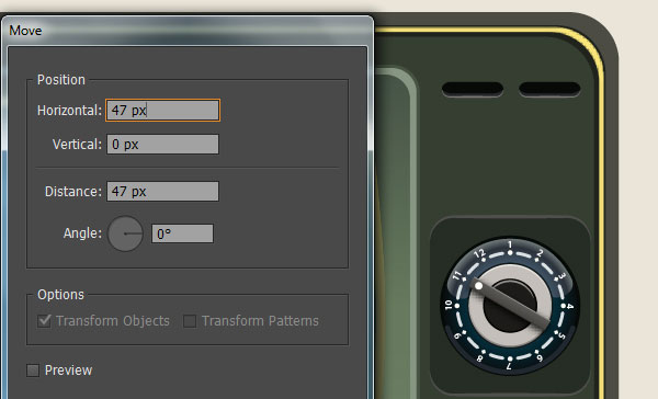
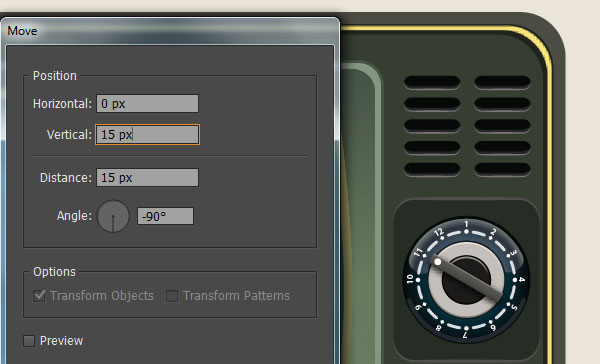
21. Place the “Speaker” group created in the step 20 to the position like you see in the first image. Keep this group selected and go to the Object > Transform > Move… Enter a 47px in the Horizontal box and click Copy. Reselect the two “Speaker” groups and open the Move dialog box again. Enter a 15px in the Vertical box and click Copy. Then press (Ctrl +D) three times to get the results like you see in the third image. Before you continue, select and group (Ctrl +G) all “Speaker” groups. Make a copy (Ctrl +C, Ctrl +F) of the newly created group and then drag the copy down and place it as shown in the last image.
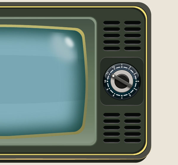
22. At this point your television should look like in the next image:.
Create the TV Antennas.
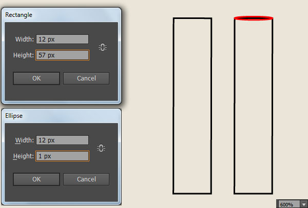
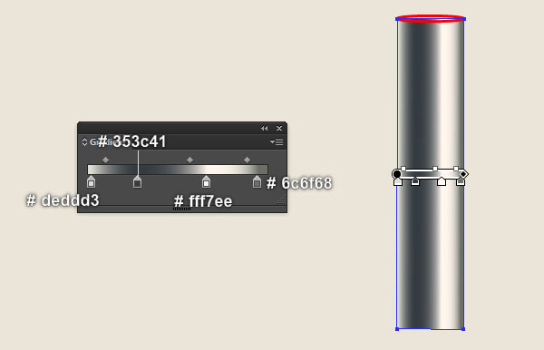
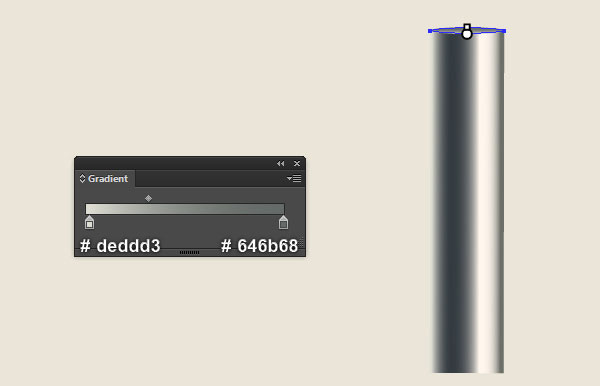
23. Pick the Rectangle Tool (M) and create a 12 by 57px black rectangle. Next pick the Ellipse Tool (L), create a 12 by 1px red ellipse and then place it to the position as shown in the second image. Now select the black rectangle created in this step, remove its stroke and fill this object with the linear gradient like you see in the third image. Continue select the red ellipse, remove its stroke and then fill this object with the linear gradient as shown in the last image. Finally select and group (Ctrl +G) two objects created in this step.
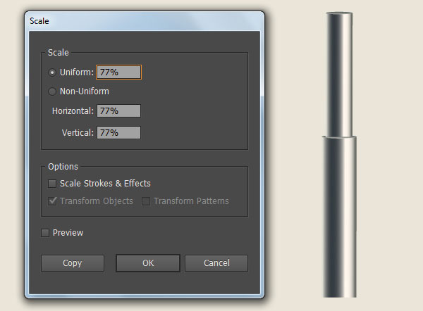
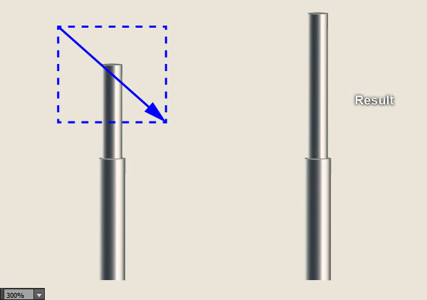
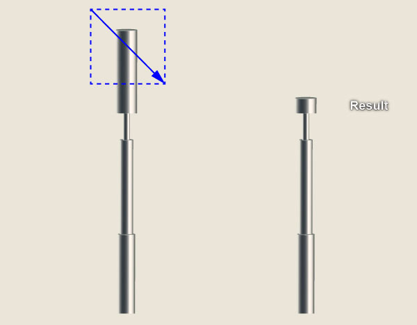
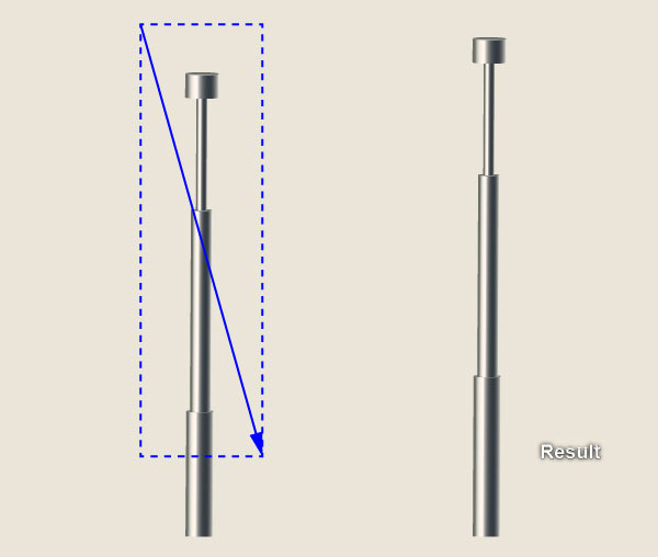
24. Select the group created in the step 23 and go to the Object > Transform > Scale… Check the Uniform, enter a 77% in the Scale box and click Copy. Then place the copy to the position like you see in the first image. Now pick the Direct Selection Tool (A), drag the mouse to the direction of the blue arrow to create a marquee as shown in the second image. This allows you to select all the points in that area. Next move all selected anchor points 24px up.
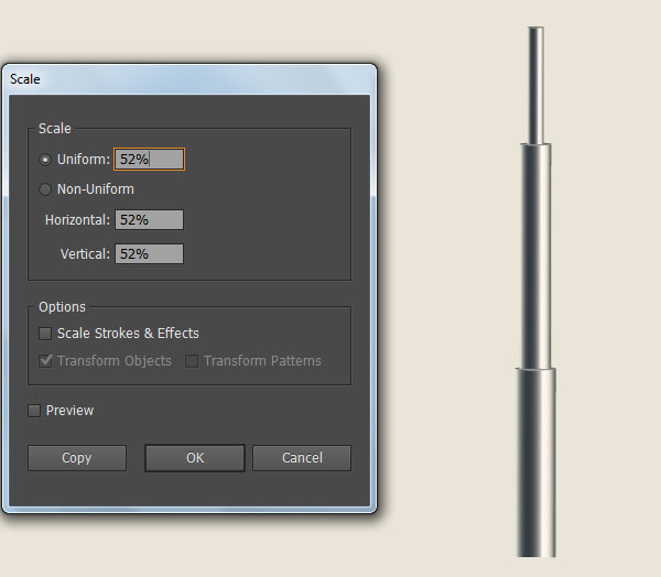
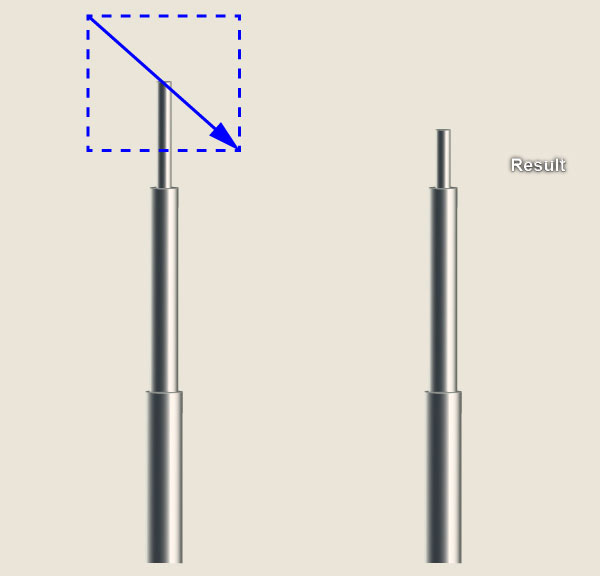
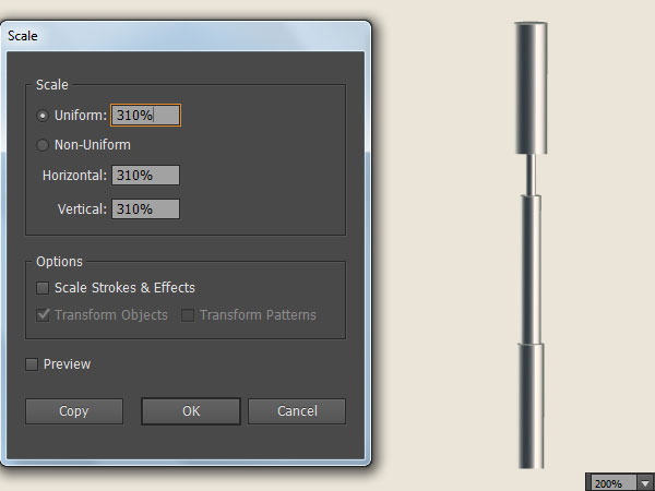
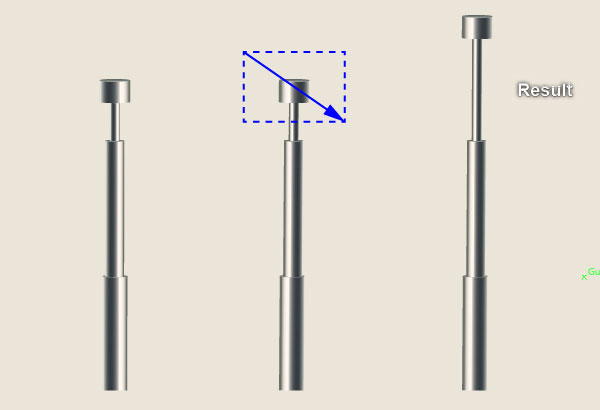
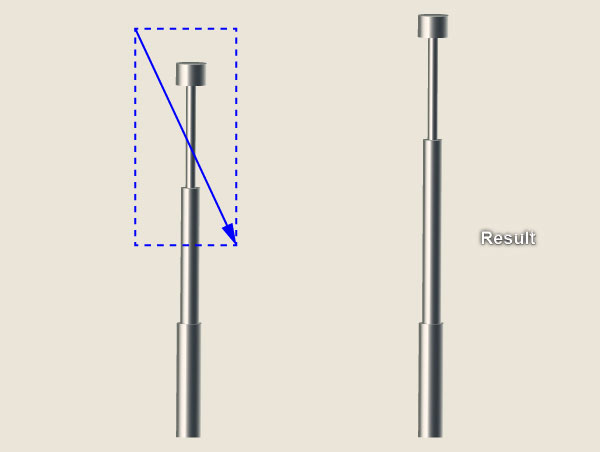
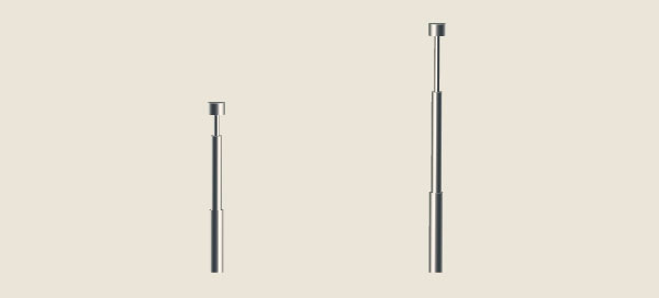
25. Select the group created in the step 24 and go to the Object > Transform > Scale… Check the Uniform, enter a 52% in the Scale box and click Copy. Then place the copy to the position like you see in the first image. Now pick the Direct Selection Tool (A), drag the mouse to the direction of the blue arrow to create a marquee as shown in the second image. This allows you to select all the points in that area. Next move all selected anchor points 26px down. Now reselect the newly created group and open the Scale dialog box again. Check the Uniform, enter a 310% in the Scale box and click Copy. Then place the copy to the position like you see in the fourth image. With the Direct Selection Tool (A), drag the mouse to the direction of the blue arrow to create a marquee as shown in the next to last image. Next move all selected anchor points 49px down. Finally select and group (Ctrl +G) all groups created from beginning step 23 to this time. The first antenna is done!
26. Next comes the second antenna. Select the first antenna and make a copy (Ctrl +C, Ctrl +F) of it, then place the copy to new position. Focus on this copy, pick the Direct Selection Tool (A), drag the mouse to the direction of the blue arrow to create a marquee as shown in the second image. This allows you to select all the points in that area. Next move all selected anchor points 32px up. Likewise, repeat the same process to create a marquee as shown in the fourth image. Then move all selected anchor points 24px up. Continue create a marquee like you see in the next to last image. Next move all selected anchor points 16px up. We are done with the second antenna for the moment.
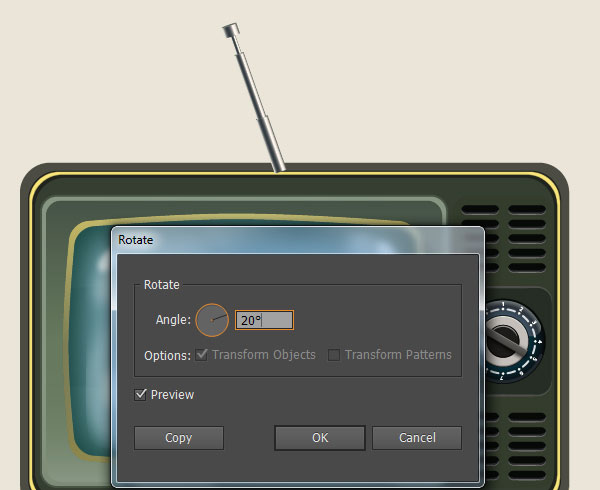
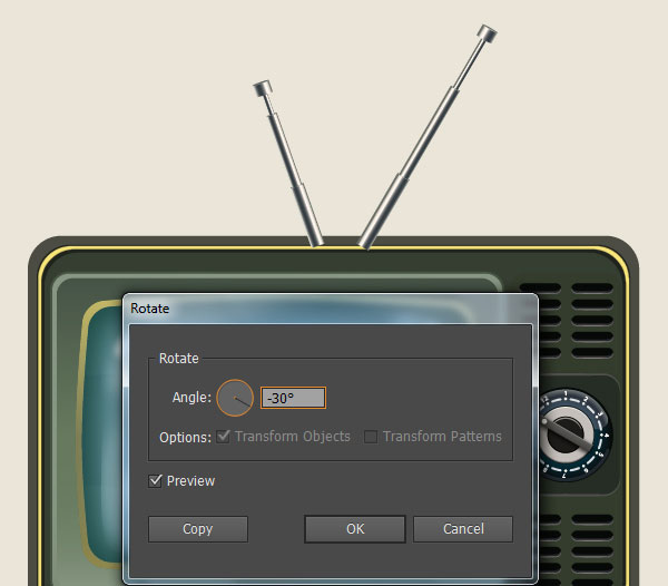
27. At this point your antennas should look like in the first image. Now select the shorter antenna and go to the Object > Transform > Rotate… Enter a 20 degrees Angle and click OK, then place this antenna to the position as shown in the second image. Continue select the remaining antenna and rotate it an angle of about -30 degrees. Then place this antenna to the position as shown in the next to last image. Finally select the two antennas and then send them to back (Ctrl +Shift +Left Square Bracket).

28. We will continue with the
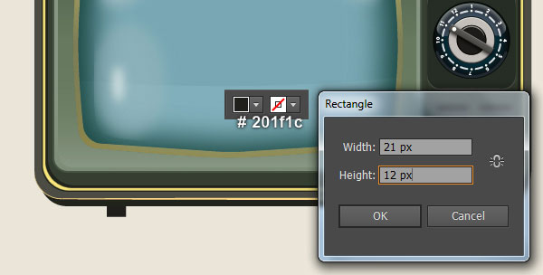
TV stand legs. Pick the Rectangle Tool (M) and create a 21 by 12px very dark yellow rectangle (# 201f1c), then place it to the position as shown in the first image. Make a copy (Ctrl +C, Ctrl +F) of the newly created rectangle and then place the copy to the position like you see in the second image.

Create the Wooden Table.
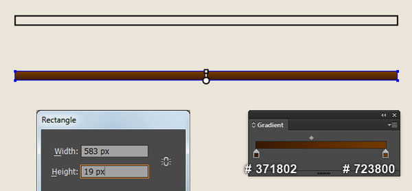
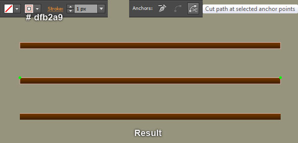
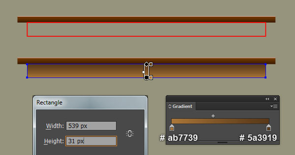
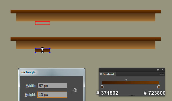
29. With the help of the Rectangle Tool (M) and the Gradient Tool (G), create a 583 by 19px dark orange rectangle. Keep the newly created rectangle selected and make a copy (Ctrl +C, Ctrl +F) of it. Still having the copy selected, swap the fill and stroke colors by clicking the bent double-headed arrow next to the Fill and Stroke color swatches in the Toolbox. Then replace the existing stroke color of the resulting rectangle with very soft red (# dfb2a9). Focus on the fourth image, select the two anchor points highlighted with green and click on the “Cut path at selected anchor points” icon from the Properties bar. This make the very soft red rectangle becomes two paths. Select and remove the lower path. Continue with the Rectangle Tool (M) and the Gradient Tool (G), create a 539 by 31px dark orange rectangle, then place it to the position as shown in the last image.
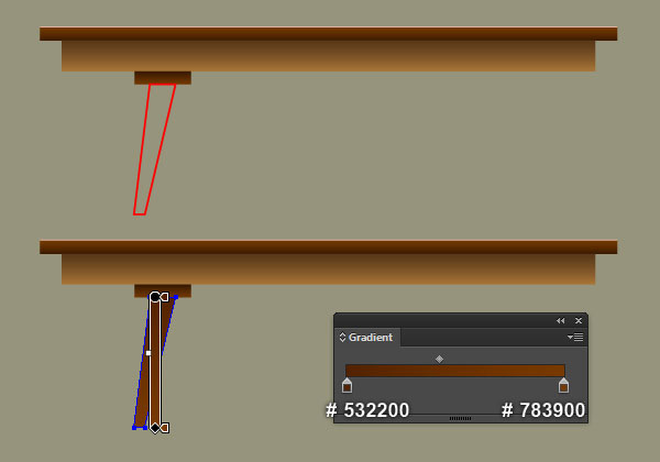
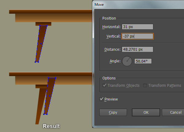
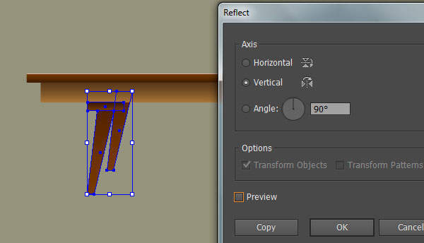
30. Pick the Rectangle Tool (M) and create a 57 by 13px red rectangle, then place it to the position as shown in the first image. Remove the stroke of the newly created rectangle and then fill it with the linear gradient like you see in the second image. Next with the help of the Pen Tool (P) and the Gradient Tool (G), create a dark orange shape as shown in the third and the fourth image. Select the newly created shape and go to the Object > Transform > Move… Enter a 31px in the Horizontal box and -37px in the Vertical box, then click Copy. Finally hide the resulting shape to back (Ctrl +Shift +Left Square Bracket).
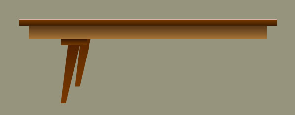
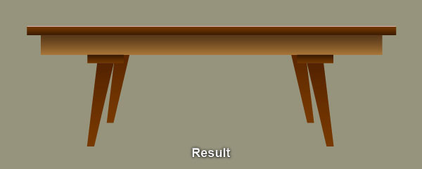
31. Select three objects created in the step 30 and go to the Object > Transform > Reflect… Check the Vertical and click Copy. Then drag the copies we have just created to the right. Don’t forget to hold the Shift key on the keyboard for straight dragging.
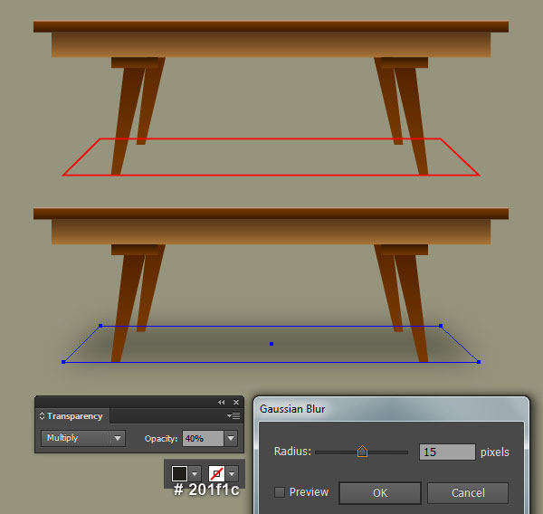
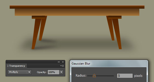
32. To give a more realistic look I’m going to be adding some shadows on some key places. Pick the Pen Tool (P) and create a red object like you see in the first image. Once your object is drawn, remove the stroke of it and fill this object with very dark yellow (# 201f1c). Apply a 15px Gaussian Blur effect for the resulting shape, then change the Blending Mode to Multiply and reduce its Opacity to 40%. Finally send the resulting shape to back (Ctrl +Shift +Left Square Bracket).
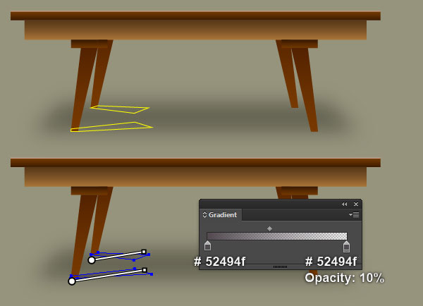
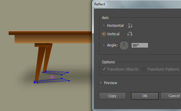
33. With the help of the Pen Tool (P) and the Gradient Tool (G). create two shapes like you see in the first and the second image. Apply a 5px Gaussian Blur effect for the newly created shapes and change the Blending Mode to Multiply. Then hide the resulting shapes behind the table. Make sure that the two shapes created in this step is still selected and go to the Object > Transform > Reflect… Check the Vertical and click Copy. Drag the copies we have just created to the right. Don’t forget to hold the Shift key on the keyboard for straight dragging.
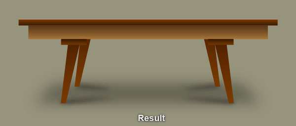
34. Select and group (Ctrl +G) all objects created from beginning step 2 to this time. At this point your illustration should look like in the next image:

Create the Background.
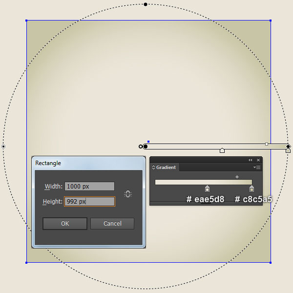
35. It’s time to draw the background. With the help of the Rectangle Tool (M) and the Gradient Tool (G), create a 1000 by 992px light grayish orange rectangle. The last thing to do is place the group created in the step 34 into the newly created background.
And We’re Done!